
Variable space page mapping method and apparatus for flash memory device

a memory device and variable space technology, applied in the direction of memory adressing/allocation/relocation, instruments, digital storage, etc., can solve the problems of occupying a small amount of space, consuming a small amount of power, and taking a relatively short read/write time, so as to improve the efficiency of garbage collection operation

Inactive Publication Date: 2010-04-01
UNIV OF SEOUL IND COOP FOUND
View PDF2 Cites 48 Cited by
  • Summary
  • Abstract
  • Description
  • Claims
  • Application Information

AI Technical Summary

Benefits of technology

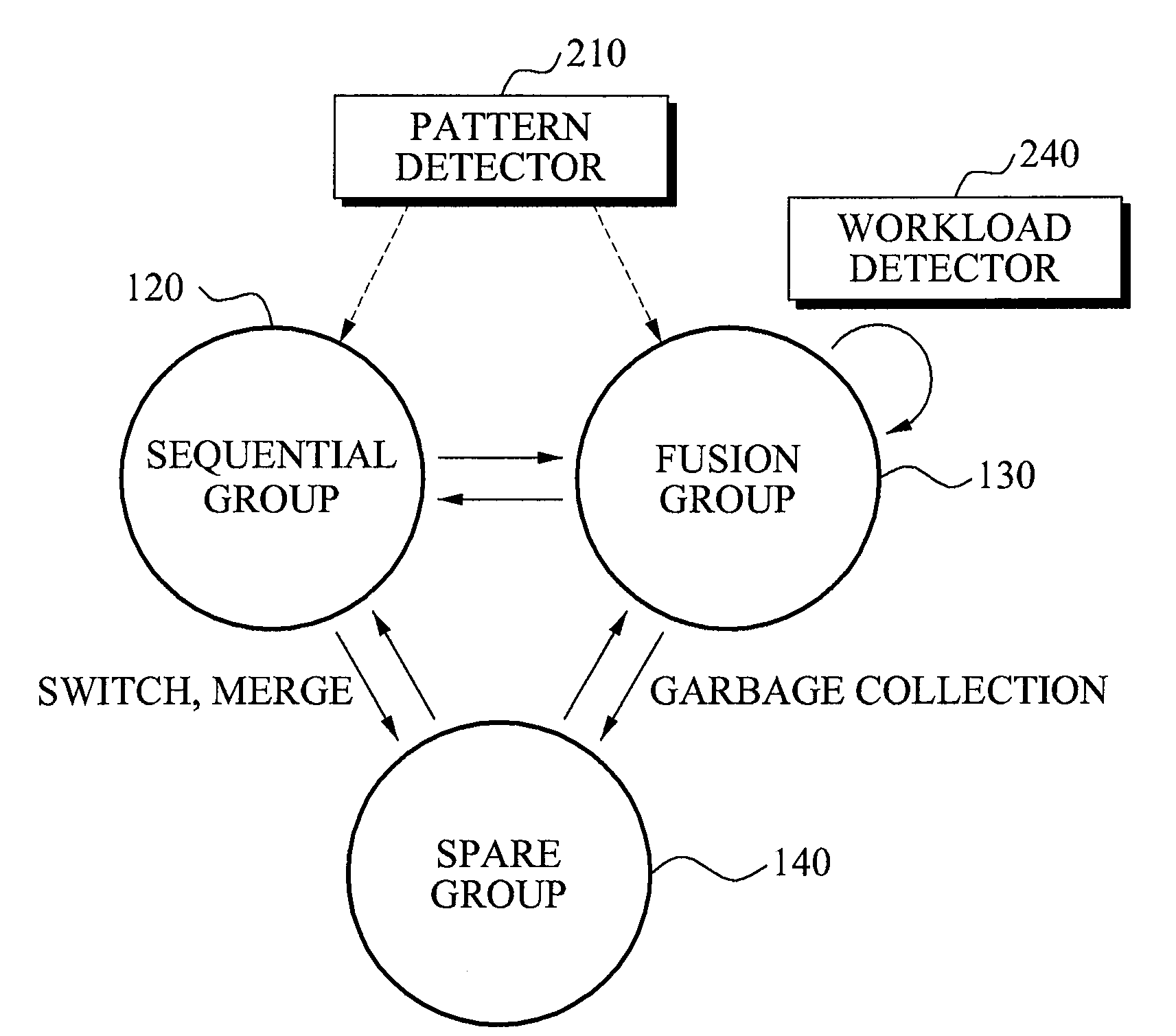
[0010]An aspect of the exemplary embodiments provides a memory management apparatus and method that may classify variable number of non-sequential blocks and redundant blocks as a fusion group to improve efficiency of a garbage collection operation that uses a limited number of redundant blocks.
[0011]Another aspect of the exemplary embodiments provides a memory management apparatus and method that may classify and separately manage a block where data is sequentially stored, to reduce a cost for reusing blocks where data is sequentially stored.
[0012]Another aspect of the exemplary embodiments provides a memory management apparatus and method that may apply a page mapping scheme in blocks classified as a fusion group, to reduce a data update cost caused by a non-sequential access operation
[0013]Another aspect of the exemplary embodiments provides a memory management apparatus and method that may determine a sequential access and a non-sequential access, and may selectively apply merge schemes or garbage collection with respect to each access operation, to reduce a data update cost for an entire non-volatile memory.
[0014]Another aspect of the exemplary embodiments provides a memory management apparatus and method that may establish a mathematical model with respect to a garbage collection cost and a data access cost, to optimize a fusion group.

Problems solved by technology

Recently, a non-volatile memory device which, compared with the magnetic disk, takes a relatively short read / write time, consumes a small amount of power, and occupies a small amount of space, has been rapidly replacing the magnetic disk as the price of the non-volatile memory decreases.

Method used


Image

  • Variable space page mapping method and apparatus for flash memory device
  • Variable space page mapping method and apparatus for flash memory device
  • Variable space page mapping method and apparatus for flash memory device

Examples


Embodiment Construction

[0026]Reference will now be made in detail to exemplary embodiments of the present invention, examples of which are illustrated in the accompanying drawings, wherein like reference numerals refer to the like elements throughout. Exemplary embodiments are described below to explain the present invention by referring to the figures.

[0027]A memory device throughout the present specification includes a non-volatile memory and a storage device storing data.

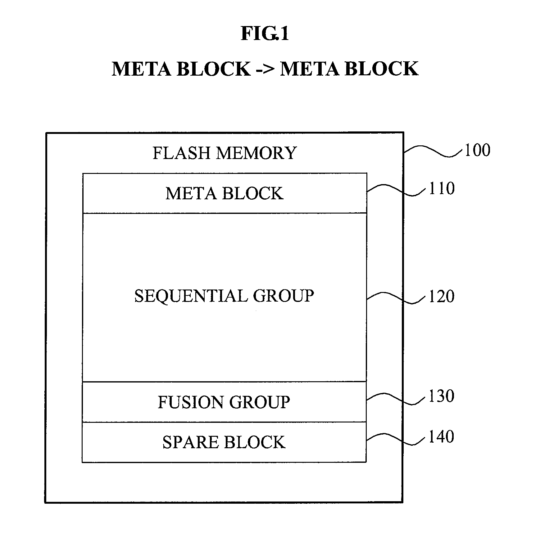
[0028]FIG. 1 illustrates an example of a flash memory 100 managed by a memory management apparatus according to an embodiment of the present invention.

[0029]The memory management apparatus may classify each of a plurality of blocks of the flash memory 100 into a meta block 110, a sequential group 120, a fusion group 130, and a redundant block(s) 140.

[0030]The meta block 110 may store information about a logical page and a logical block mapped to each of the plurality of blocks in the flash memory 100, and may store information required...


PUM


Abstract

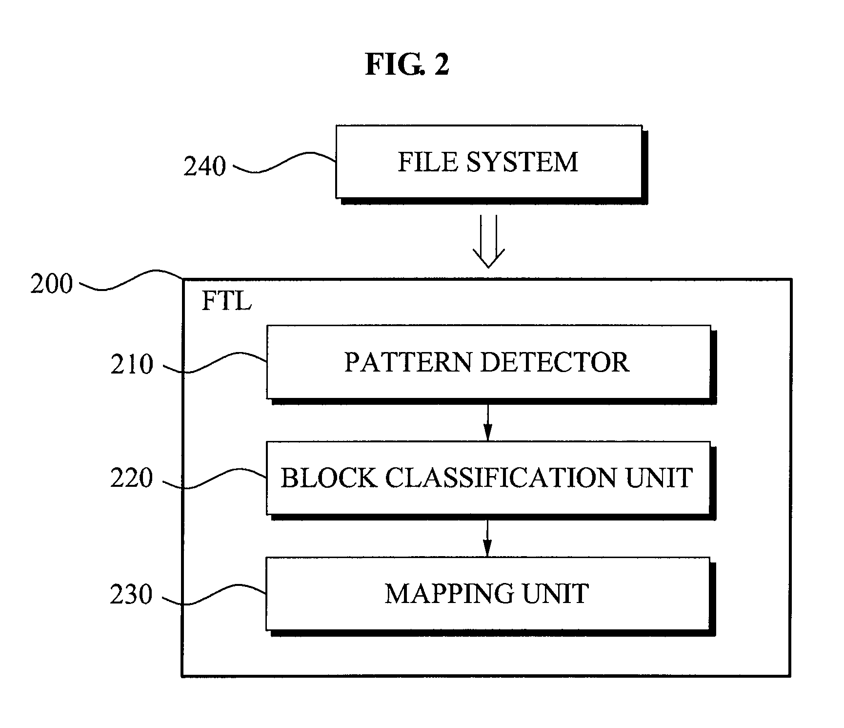
Disclosed is a method and apparatus embodying a flash translation layer (FTL) in a storage device including a flash memory. The FTL may classify a block into a sequential group and a fusion group based on a locality of a write request. The FTL may store data in blocks of the fusion group by using a page mapping scheme, and sequentially store data by using a block mapping scheme. The FTL may improve efficiency of garbage collection operation that is performed by using limited redundant blocks and also may increase efficiency of a non-sequential reference operation.

Description

CROSS-REFERENCE TO RELATED APPLICATION[0001]This application claims the benefit of Korean patent application No. 10-2008-0096581, filed on Oct. 1, 2008, in the Korean Intellectual Property Office, the disclosure of which is incorporated herein by reference.BACKGROUND OF THE INVENTION[0002]1. Field of the Invention[0003]The following description relates to a memory device and a management method for the memory device, and more particularly, to a non-volatile memory-based memory device and a management method for the memory device.[0004]2. Description of Related Art[0005]Examples of a storage device storing data include a magnetic disk, a semiconductor device, and the like. Since physical characteristics are different for each type of storage device, a management method corresponding to the physical characteristic is required.[0006]Conventionally, the magnetic disk is widely used. A read / write time of the magnetic disk takes an average of several milliseconds per kilobyte. Also, the r...

Claims


Application Information

Patent Timeline
IPC IPC(8): G06F12/02
CPCG06F12/0246G06F2212/7202G06F2212/7201G06F12/04G06F12/06
Inventor KWON, HUNKIKIM, EUNSAMCHOI, JONGMOOLEE, DONGHEENOH, SAM H.
Owner UNIV OF SEOUL IND COOP FOUND
Learn More