Prognostic diagnostic capability tracking system

a technology of diagnostic capability and tracking system, which is applied in the direction of error detection/correction, testing/monitoring control system, instruments, etc., can solve the problems of mechanics or maintenance personnel at a loss to determine solely from the indicator, the engine light illumination is not immediately apparent, and the mechanic or maintenance personnel are at a loss to determine which one item needs to be repaired or replaced, etc., to reduce the time it takes, reduce unnecessary ordering and replacement of parts, and eliminate the effect of transpor

Active Publication Date: 2010-04-01
BAE SYST INFORMATION & ELECTRONICS SYST INTERGRATION INC
View PDF9 Cites 48 Cited by
  • Summary
  • Abstract
  • Description
  • Claims
  • Application Information

AI Technical Summary

Benefits of technology

[0017]In order to solve the problem of multiple platforms and real-time requirements a universal on-board system is provided for automatic fault detection and on-the-spot repair instructions that includes a module adapted to be coupled to a wide variety of platforms and Line Replaceable Units (LRU). The system offers step by step repair instructions through the use of multiple levels of diagnosis involving rapid, accurate evaluation of the state of the platform or LRU to which the module is coupled, with the system isolating the unique likely cause of failure for any detected fault. Once the unique cause is determined, detailed targeted repair instructions are provided to address the cause of the fault, with the repair instructions optionally including video instructions. The fault cause accuracy and resulting targeted repair instructions significantly reduce the time it takes to analyze a fault in the field to find its cause, and both reduces unnecessary ordering and replacement of parts, and in some cases can eliminate transporting the LRU to a repair depot.

Problems solved by technology

While maintenance manuals exist to assist mechanics and maintenance personnel to determine the cause of a fault and to fix it, there is oftentimes a misconception that when a fault indication occurs, one immediately knows the cause of the fault.
However, the cause of the engine light illumination is not immediately apparent from the fault indication.
Thus many fault detection systems do not explain the root cause of the system fault so that it is impossible to ascertain which one item needs to be repaired or replaced.
As a result, mechanics or maintenance personnel are at a loss to determine solely from the indicator the cause of the fault.
Maintenance manuals and external software tools help but often lead the maintainer down a path of trial and error.
This can result in indiscriminate swapping out of parts which removes the part as an available spare and oftentimes results in the breakage of the parts that are being swapped out; and this occurs as much as fifty percent of the time.
Moreover, the industry estimates that for a large number of fault indications, the fault indicators are not necessarily valid.
Thus, mechanics or maintenance personnel oftentimes do not know what to do in the face of failure indicators and oftentimes send failed units directly back to the manufacturer.
While a large number of field manuals exist, they are not necessarily as useful as they might be because of the massive amounts of information in the manual and that included diagnostic strategies were developed without access to the range of failure situations that can occur.
Thus, a soldier in the field upon feeling a rough running engine may be in a quandary as to whether or not the engine is fixable on-the-spot, whether the vehicle can be run as-is, or whether the vehicle must be returned to a maintenance depot.
For instance, for a rough-running engine it is not clear whether the rough running engine will propel the vehicle up an incline so that it can keep going, or whether by continuing to run the vehicle, further damage to the vehicle will occur, or the vehicle will completely fail.
Although the Boeing system does employ an on-board system, this on-board system does not detect faults, but merely collects data.
Finally, since the Pattipati fault isolation system is off-board, its interfaces cannot be adapted for different platforms and is merely a replacement for maintenance manuals.
Moreover, the Honeywell system is not adaptable to various platforms absent reprogramming.
As such they are stand alone systems and do not address the special requirements and architectural constraints necessary to execute model-based diagnostics on various platforms in real-time.

Method used


Image

  • Prognostic diagnostic capability tracking system
  • Prognostic diagnostic capability tracking system
  • Prognostic diagnostic capability tracking system

Examples


Embodiment Construction

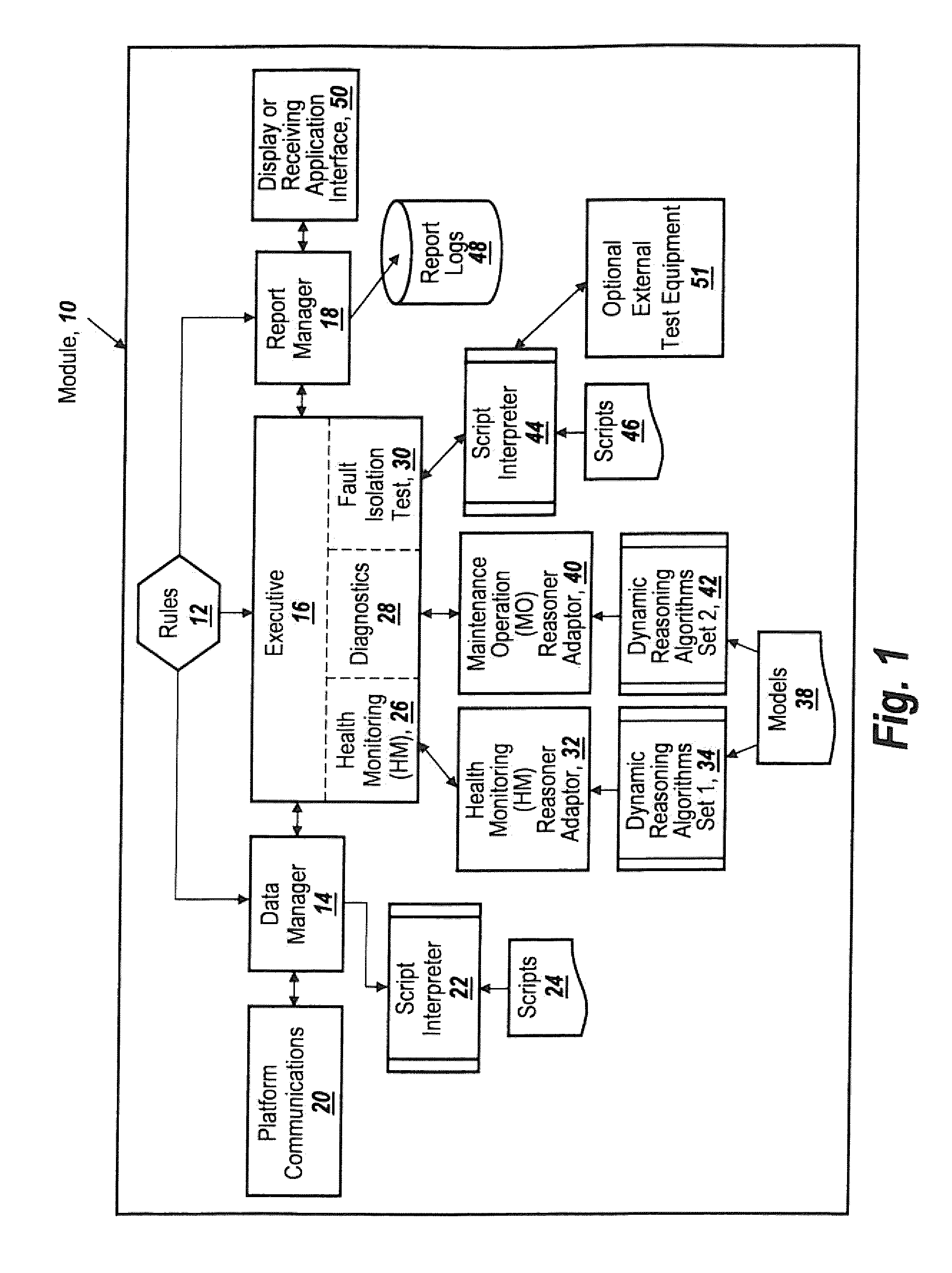
[0050]Referring now to FIG. 1, a module 10 is either embedded or connected to a platform or LRU which performs a prognostic and diagnostic function to detect faults and to analyze and diagnose the causes of the faults of the platform to which it is coupled.

[0051]In order for the module to adapt to any of a wide variety of applications, module 10 is provided with a rules engine 12 which is coupled to a data manager 14, an executive program 16 and a report manager 18.

[0052]The rules are modified or adapted for each of the platforms or LRUs the module is to monitor, with platform communications 20 connecting module 10 to the particular platform involved.

[0053]Data manager 14 is coupled to a script interpreter 22 which is provided with scripts 24, thus to be able to translate the platform communications format to a universal format usable by module 10 as well as to perform translation, and transformation of the input data.

[0054]Executive program 16 controls three functions, namely a hea...


PUM


Abstract

A universal on-board system is provided for automatic fault detection and on-the-spot repair instructions that includes a module adapted to be coupled to a wide variety of platforms and Line Replaceable Units.

Description

RELATED APPLICATIONS[0001]This Application claims rights under 35 USC §119(e) from U.S. Application Ser. No. 61 / 100,459 filed Sep. 26, 2008, the contents of which are incorporated herein by reference.FIELD OF THE INVENTION[0002]This invention relates to a prognostic, diagnostic capability tracking system and more particularly to a universal application-adaptable on-board module which may be coupled to a wide variety of platforms (land vehicles, aircraft, ships) that detects faults, and without human intervention controls the platform to analyze and diagnose the causes of platform faults and provide immediately-accessible repair instructions based on a determination of the unique likely cause of a failure.BACKGROUND OF THE INVENTION[0003]In both military and commercial environments, platforms or Line Replaceable Units, LRUs, often fail in the field and it is up to maintenance personnel to be able find a fault, determine its cause and repair the platform or LRU. This usually involves ...

Claims


Application Information

Patent Timeline
Patent Type & Authority Applications(United States)
IPC IPC(8): G06F11/07
CPCG05B23/0275G06F11/079G06F11/0739G06F11/0727
Inventor SPIER, CAROLYNMILLS, DANIEL E.
Owner BAE SYST INFORMATION & ELECTRONICS SYST INTERGRATION INC
Why Eureka
Try Eureka