Piezoelectric Element and Method for Manufacturing the Piezoelectric Element

a piezoelectric element and piezoelectric technology, applied in the field of piezoelectric elements, can solve the problems of difficult universally giving a reduction resistance to pzt compounds, piezoelectric properties may be degraded, piezoelectric elements may lose their function, etc., and achieve the effect of facilitating the formation of the desired piezoelectric ceramic body

Active Publication Date: 2010-04-08
MURATA MFG CO LTD
View PDF4 Cites 1 Cited by
  • Summary
  • Abstract
  • Description
  • Claims
  • Application Information

AI Technical Summary

Benefits of technology

[0020]Accordingly, an object of the invention is to provide an inexpensive monolithic piezoelectric element having such a piezoelectric property as it can be properly used in practice even though it has been fired in a reducing atmosphere.
[0021]The present inventors have conducted intensive research to accomplish the object, focusing on alkali metal niobate-based compounds, and have found that alkali metal niobate-based compounds are not reduced and can maintain their piezoelectric property even by being fired in reducing atmospheres. Furthermore, the inventors have found through their subsequent intensive research that the piezoelectric property can be maintained even by firing a base metal for the internal electrode and a piezoelectric ceramic composition together in a reducing atmosphere.
[0026]The method according to the present invention produces a piezoelectric element including a piezoelectric ceramic body containing an internal electrode. The method includes the step of preparing a piezoelectric ceramic material mainly containing a perovskite complex oxide containing an alkali metal niobate-based compound and forming the piezoelectric ceramic material into compacts having a predetermined shape, the step of applying an electroconductive paste for forming the internal electrode onto the compacts, the step of stacking the compacts onto which the electroconductive paste has been applied to form a multilayer structure, and the step of co-sintering the multilayer structure in a reducing atmosphere. Thus, this method facilitates the formation of a desired piezoelectric ceramic body containing an internal electrode co-sintered in a reducing atmosphere, and easily provides a monolithic piezoelectric element capable of being used in practice.

Problems solved by technology

It is difficult to universally give a reduction resistance to PZT compounds, and besides they can be reduced by firing in a reducing atmosphere at high probability.
Accordingly, the piezoelectric properties may be degraded or the resulting piezoelectric element may lose its function.

Method used


Image

  • Piezoelectric Element and Method for Manufacturing the Piezoelectric Element
  • Piezoelectric Element and Method for Manufacturing the Piezoelectric Element
  • Piezoelectric Element and Method for Manufacturing the Piezoelectric Element

Examples


example 1

[0064]K2CO3, Na2CO3, and Nb2O5 were prepared as ceramic raw materials and were weighed out so as to prepare a piezoelectric ceramic composition whose main constituent was expressed by a compositional formula (K0.5Na0.5)NbO3.

[0065]Then, the weighed material was placed together with ethanol in a ball mill containing PSZ and was wet-mixed for about 4 hours. After being dried, the mixture was calcined at a temperature of 700 to 900° C. to yield a calcined material.

[0066]Then, 100 parts by weight of the calcined material, 10 parts by weight of vinyl acetate resin as a binder, and 100 parts by weight of water were placed in a ball mill containing PSZ, and a an appropriate amount of plasticizer was further added. The materials were wet-mixed for 4 hours and thus a ceramic slurry was prepared.

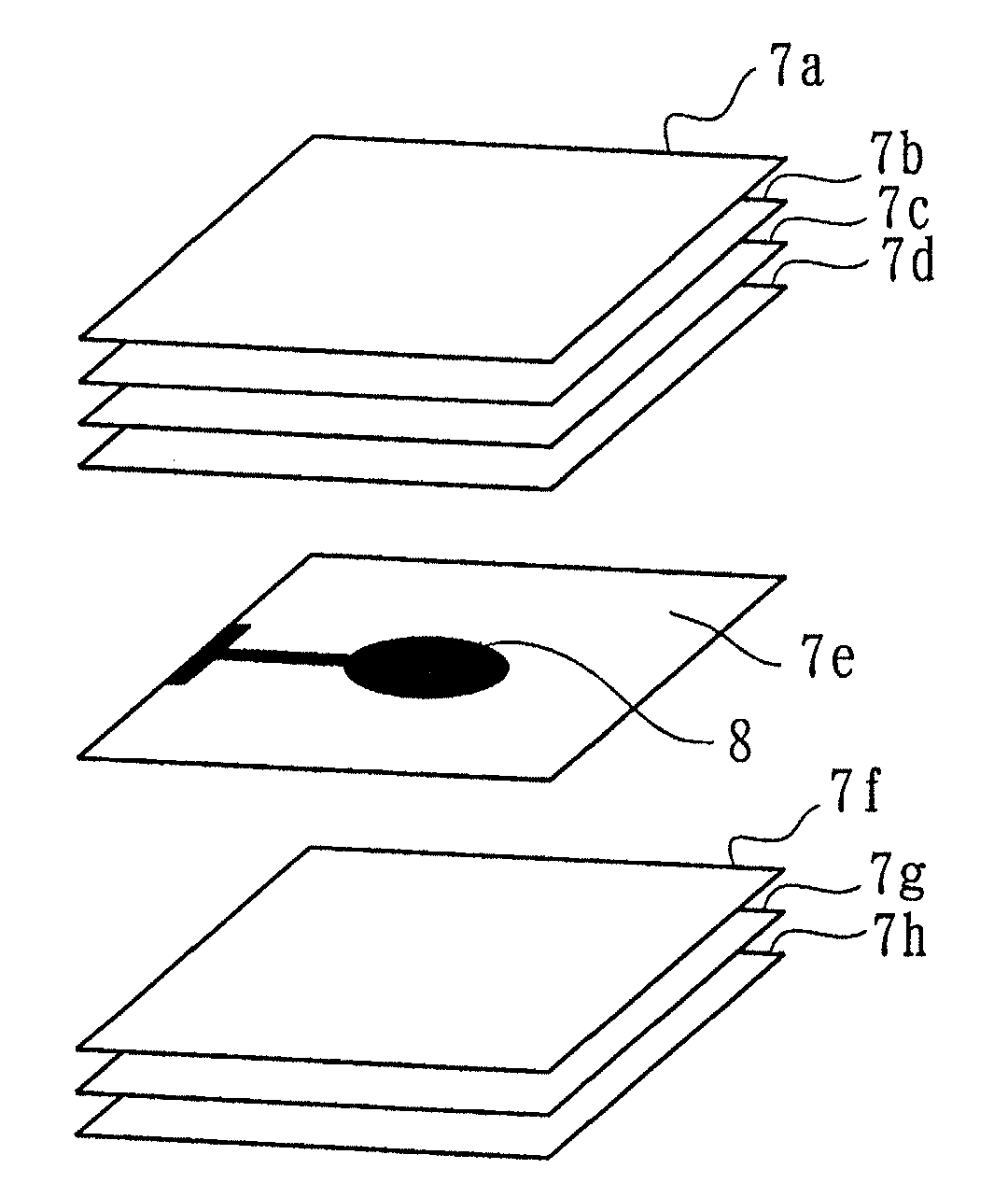
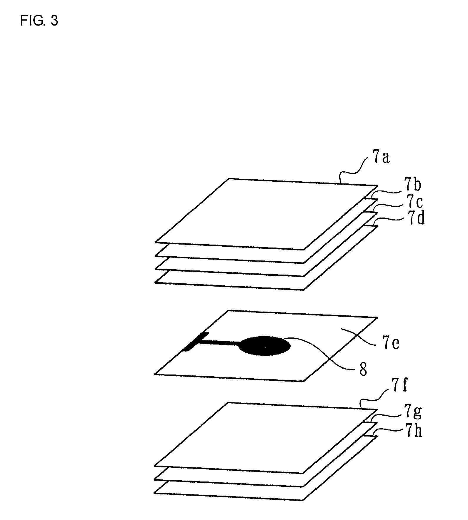
[0067]The ceramic slurry was formed into a compact by a doctor blade method. The compact was cut into a plurality of ceramic green sheets of 10 mm in length, 10 mm in width, and 50 μm in thickness.

[006...

example 2

[0075]A test piece of Example 2 was prepared in the same manner and the same procedure as in Example 1 except that K2CO3, Na2CO3, Li2CO3, and Nb2O5 were prepared as ceramic raw materials and were weighed out so as to prepare a piezoelectric ceramic composition whose main constituent was expressed by a compositional formula (K0.475Na0.475Li0.05)NbO3.

[0076]The firing was performed at 1050° C. for 2 hours.

example 3

[0077]A test piece of Example 3 was prepared in the same manner and the same procedure as in Example 1 except that K2CO3, Na2CO3, Li1CO3, Nb2O5, and Ta2O5 were prepared as ceramic raw materials and were weighed out so as to prepare a piezoelectric ceramic composition whose main constituent was expressed by a compositional formula (K0.5Na0.5)(Nb0.9Ta0.1)O3. The firing was performed at 1050° C. for 2 hours.


PUM

PropertyMeasurementUnit
temperatureaaaaaaaaaa
temperaturesaaaaaaaaaa

Abstract

A piezoelectric element includes a piezoelectric ceramic body containing an internal electrode. The piezoelectric ceramic body is mainly made of a perovskite complex oxide containing an alkali metal niobate-based compound containing at least one element selected from among K, Li, and Na. The internal electrode is made of a base metal material, such as Ni or Cu. The piezoelectric element is produced by co-sintering the internal electrode and the piezoelectric ceramic body. Thus, there is provided an inexpensive piezoelectric element that can be properly used in practice even though it has been fired in a reducing atmosphere.

Description

CROSS REFERENCE TO RELATED APPLICATIONS[0001]The present application is a divisional of application Ser. No. 11 / 856,914, filed Sep. 18, 2007, which is a continuation of International Application No. PCT / JP2005 / 023247, filed Dec. 19, 2005, and claims priority to Japanese Patent Application No. JP2005-086102, filed Mar. 24, 2005, the entire contents of each of these applications being incorporated herein by reference in their entirety.FIELD OF THE INVENTION[0002]The present invention relates to piezoelectric elements, and more specifically to a monolithic piezoelectric element including a piezoelectric ceramic body containing an internal electrode and a method for manufacturing the piezoelectric element.BACKGROUND OF THE INVENTION[0003]A variety of piezoelectric elements are increasingly used in electronic apparatuses as the electronic technology is being developed. Among such piezoelectric elements, monolithic piezoelectric elements are manufactured as below.[0004]First, a piezoelect...

Claims


Application Information

Patent Timeline
Patent Type & Authority Applications(United States)
IPC IPC(8): H01L41/24C04B35/00H01L41/09H01L41/187H01L41/273H01L41/39H01L41/43H02N2/18H03H3/02H03H9/17
CPCC01G33/006Y10T29/49163C01P2006/32C01P2006/40C04B35/491C04B35/493C04B35/495C04B2235/3201C04B2235/3203C04B2235/3208C04B2235/3251C04B2235/6025C04B2235/652C04B2235/656C04B2235/6582H01L41/083H01L41/1873H01L41/273H03H9/178Y10T29/42C01P2002/34H10N30/8542H10N30/50H10N30/053
Inventor KIMURA, MASAHIKOSHIRATSUYU, KOSUKETAKEDA, TOSHIKAZUWADA, NOBUYUKI
Owner MURATA MFG CO LTD
Why Eureka
Try Eureka