Objective lens driving apparatus, optical pickup, and information recording / reproducing apparatus

a technology of optical pickups and driving apparatuses, applied in the direction of optical recording heads, instruments, data recording, etc., can solve the problems of reducing the thrust force reduce the pitching resonance and the yawing resonance, and reduce the resonance

Inactive Publication Date: 2009-10-22
PIONEER CORP
View PDF3 Cites 2 Cited by
  • Summary
  • Abstract
  • Description
  • Claims
  • Application Information

AI Technical Summary

Benefits of technology

[0027]Then, in an aspect of the focusing-drive, the lens holder may be supported by the pair of linear suspension springs and may be driven by the driving device so as to relatively reduce a pitching resonance and a yawing resonance, the pitching resonance being possibly generated in driving in the tracking direction, the yawing resonance being possibly generated in driving in the focusing direction.
[0028]According to this aspect, it is effective in the case where the tracking drive and the focusing drive are both performed, as seen often in practice. That is, even if it is relatively hard to reduce the resonances related to the both driving, the lens holder is supported by the pair of linear suspension springs and is driven by the driving device so as to relatively reduce the pitching resonance and the yawing resonance. Thus, the both resonances are reduced or eliminated.

Problems solved by technology

However, the objective lens driving apparatuses disclosed in the patent documents 1 and 2 possibly have the following technical problem.
In addition, according to the technology associated with the parallel structure disclosed in the patent document 2, in order to cancel the rotational moment, a force in an opposite direction to a thrust direction is intentionally generated, so that there is such a technical problem that a thrust force is reduced.

Method used


Image

  • Objective lens driving apparatus, optical pickup, and information recording / reproducing apparatus
  • Objective lens driving apparatus, optical pickup, and information recording / reproducing apparatus
  • Objective lens driving apparatus, optical pickup, and information recording / reproducing apparatus

Examples


first embodiment

(1) First Embodiment

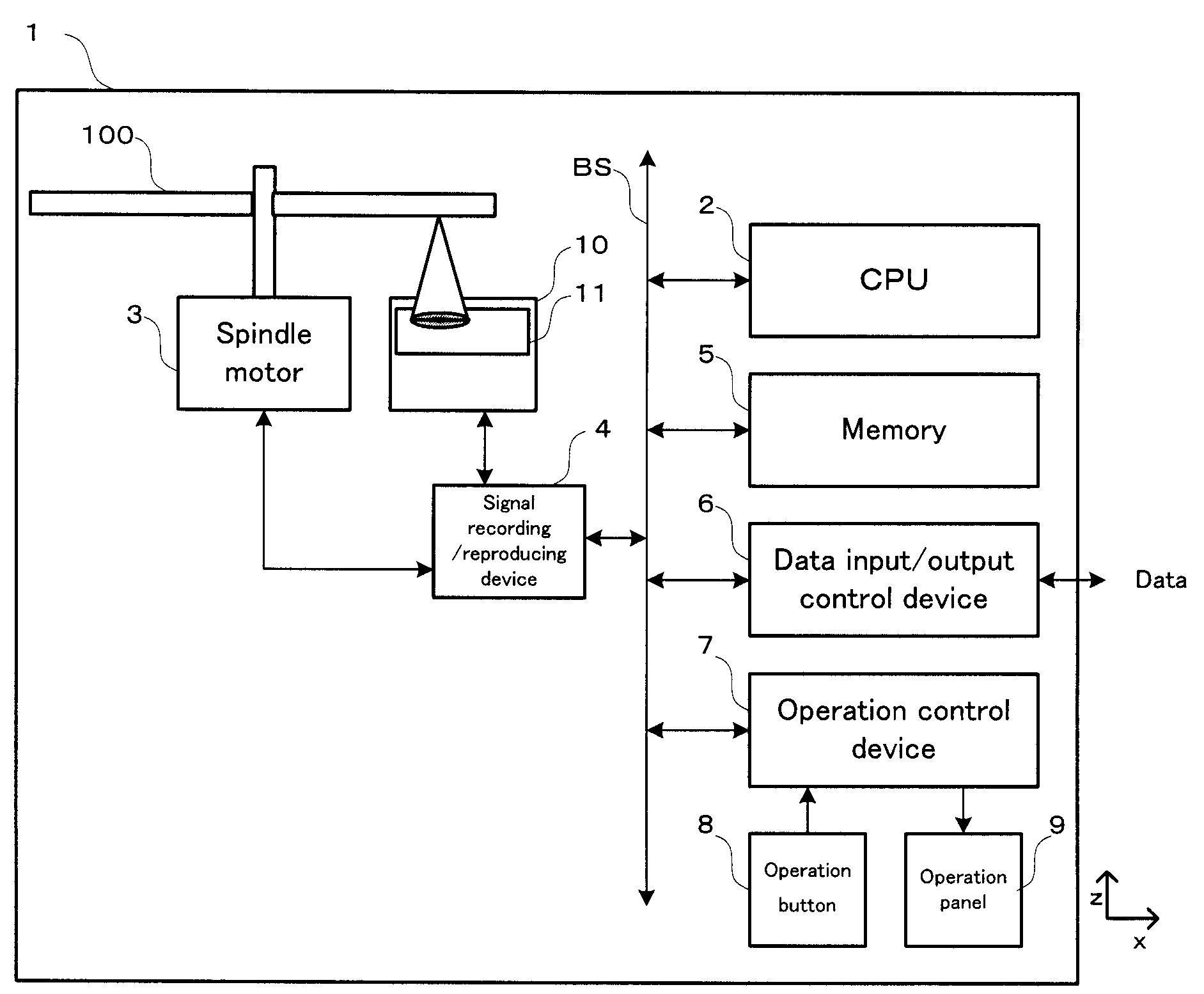
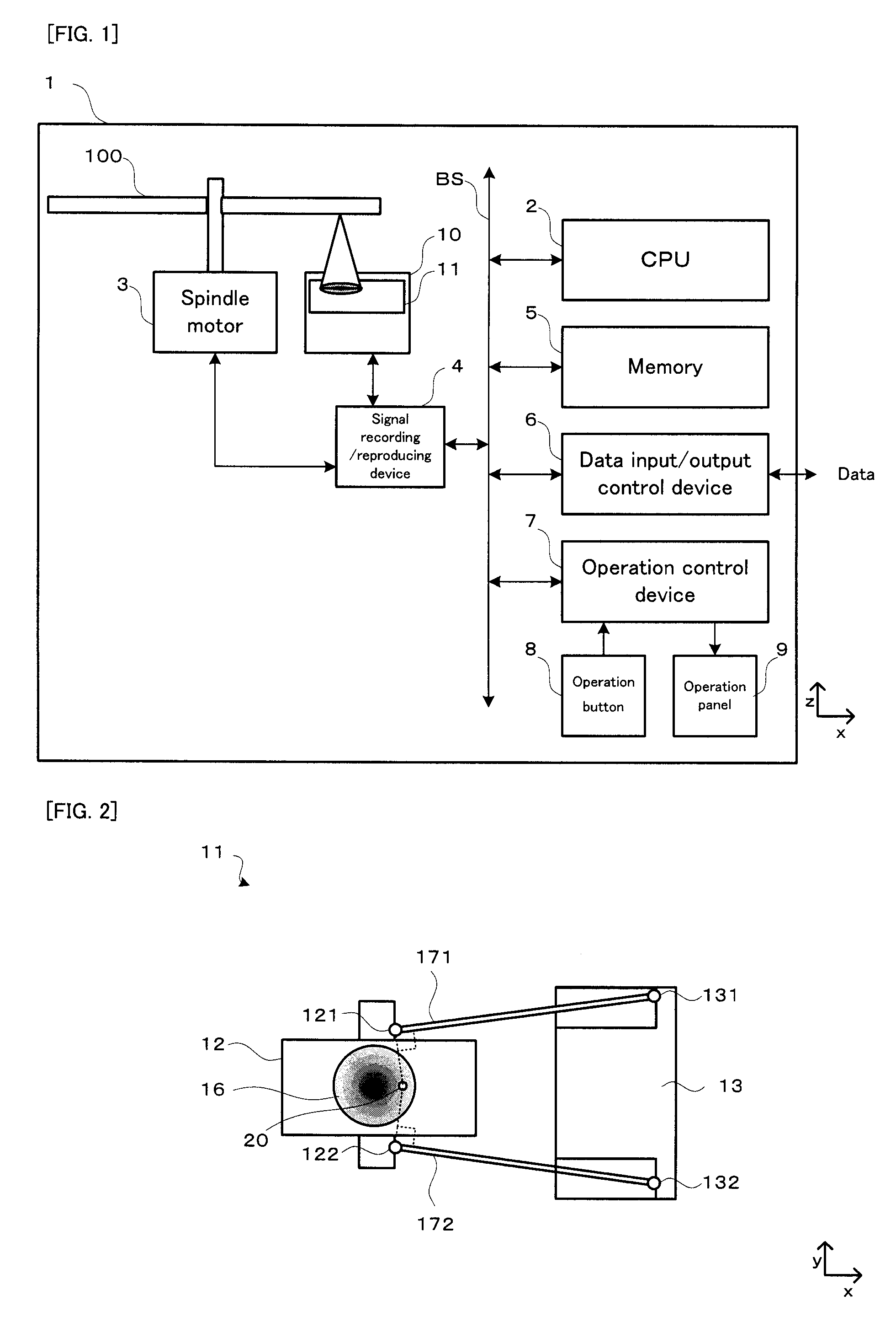
[0083]With reference to FIG. 1 to FIG. 5, an explanation will be given on the structure and operation process of an objective lens driving apparatus in a first embodiment. FIG. 1 is a block diagram conceptually showing the basic structure of the information recording / reproducing apparatus provided with the objective lens driving apparatus in the first embodiment of the present invention.

[0084]In FIG. 1, an information recording / reproducing apparatus 1, which is one example of the “information recording / reproducing apparatus” of the present invention, is provided with: an optical pickup 10; an objective lens driving apparatus 11; a spindle motor 3; a signal recording / reproducing device 4; a CPU 2; a memory 5; a data input / output control device 6; an operation control device 7; and the like. Under the control of the CPU 2, the information recording / reproducing apparatus 1 records information onto an optical disc 100 and reads the information recorded on the optical...

second embodiment

(2) Second Embodiment

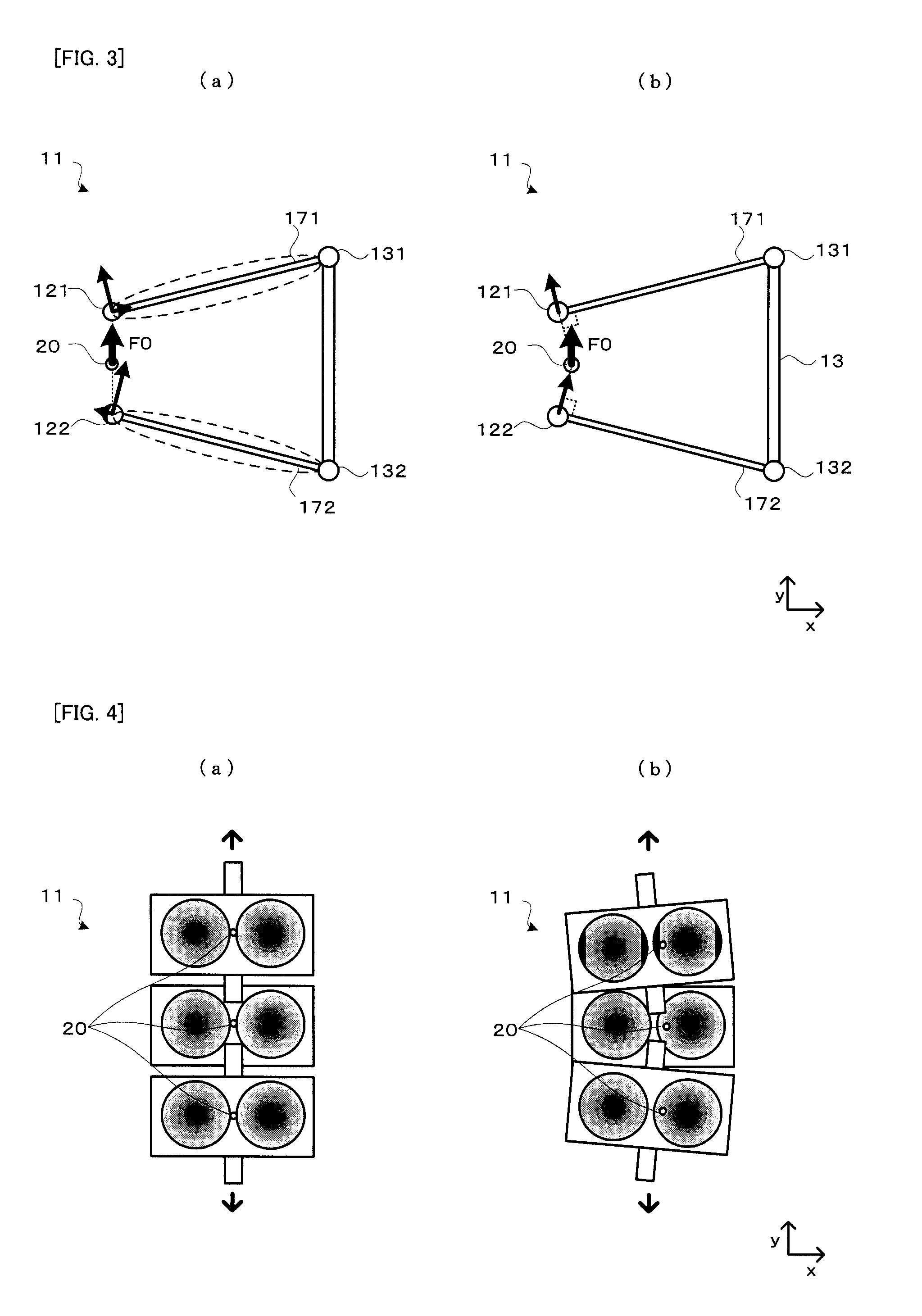
[0109]Next, with reference to FIG. 5 and FIG. 6 in addition to FIG. 1, an explanation will be given on the structure and operation process of an objective lens driving apparatus 11 in a second embodiment. Incidentally, in FIG. 5 and FIG. 6, the same structure as that in the aforementioned drawings carries the same numerical reference, and the explanation thereof will be omitted as occasion demands. FIG. 5 is a perspective view showing the link model of the objective lens driving apparatus having two suspension springs in the first embodiment. FIG. 6 is a perspective view showing the link model of an objective lens driving apparatus having four suspension springs in a second embodiment.

[0110]In the embodiment, in particular, what is different from the first embodiment is the position of the suspension center 20, coming from a difference in the number and arrangement of the suspension springs. Specifically, the suspension springs in the embodiment (refer to FIG. 6...

third embodiment

(3) Third Embodiment

[0113]Next, with reference to FIG. 7 to FIG. 9 in addition to FIG. 2, an explanation will be given on the structure and operation process of an objective lens driving apparatus 11 in a third embodiment. Incidentally, in FIG. 7 to FIG. 9, the same structure as that in the aforementioned drawings carries the same numerical reference, and the explanation thereof will be omitted as occasion demands. FIG. 7 are plan views conceptually showing the basic structure of an objective lens driving apparatus by a magnet method in a third embodiment. FIG. 8 are characteristic diagrams conceptually showing the basic structure of an objective lens driving apparatus by a magnet method in a third embodiment. FIG. 9 are characteristic diagrams showing the frequency characteristic of the objective lens driving apparatus in the third embodiment. More specifically, FIG. 7(a) shows the basic structure of the objective lens driving apparatus 11 in a comparison example. FIG. 8(a) shows a...


PUM

PropertyMeasurementUnit
rotation frequencyaaaaaaaaaa
angleaaaaaaaaaa
distanceaaaaaaaaaa

Abstract

An objective lens driving device is provided with an objective lens; a lens holder for holding the objective lens; a pair of linear suspension springs for supporting the lens holder at each one end; a spring holder whereupon the other ends the springs are fixed; and a driving means for at least driving the objective lens in a tracking direction together with the lens holder. The linear suspension springs have narrowed or widened end compared with the other end in plan view from an optical axis direction. The lens holder is supported to be driven in the tracking direction, by having the cross point of the two lines, which pass the suspension spring ends on one side and are vertical to the extending directions of the linear suspension springs, respectively, at the driving center.

Description

TECHNICAL FIELD[0001]The present invention relates to an objective lens driving apparatus, an optical pickup, and an information recording / reproducing apparatus capable of eliminating or reducing a resonance possibly generated when recording or reproduction is performed on an optical disc, such as a CD (Compact Disc), DVD, BD (Bu-ray Disc), or HD (High Definition)-DVD.BACKGROUND ART[0002]This type of objective lens driving apparatus (i.e. actuator) is provided with a focus driving mechanism for driving an objective lens in a focusing direction of an optical disc, in order to focus a light spot on a track of the optical disc. In addition, in order to make the light spot follow the track of the optical disc, it is provided with a tracking driving mechanism for driving the objective lens in a tracking direction of the optical disc. At this time, along with the focus displacement or tracking displacement, the objective lens possibly gets an inclination. Moreover, synchronizing a rolling...

Claims


Application Information

Patent Timeline
Patent Type & Authority Applications(United States)
IPC IPC(8): G11B7/00
CPCG11B7/0932
Inventor GOAMI, KAZUTAKA
Owner PIONEER CORP
Why Eureka
Try Eureka