
Beverage bottling plant for filling bottles with a liquid beverage material having a filling machine

a technology of beverage bottling plant and filling machine, which is applied in the direction of liquid handling, packaging goods, transportation and packaging, etc., can solve the problems of sputtering of the return gas tube, after-running liquid above the valve seat, and no longer possible gas escape back into the pressure vessel

Inactive Publication Date: 2010-04-08
KHS GMBH
View PDF5 Cites 6 Cited by
  • Summary
  • Abstract
  • Description
  • Claims
  • Application Information

AI Technical Summary

Benefits of technology

[0016]The object is to substantially eliminate or minimize the effects of the disadvantages described above. For this purpose the present application teaches a filling valve that is equipped with a gas cutoff with a swirling action, whereby the gas cutoff is realized essentially in the form of a flat element.

Problems solved by technology

Consequently, a further escape of the gas back into the pressure vessel is no longer possible.
On such filling mechanisms there is a risk that the quantity of gas that is above the surface of the liquid will bubble up through the liquid duct, which is still open, and will thereby cause an after-running of the liquid that is above the valve seat.
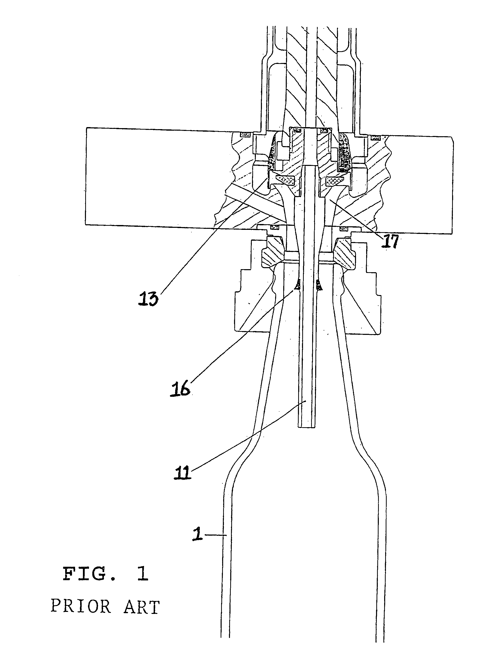
If the liquid should flow along the return gas tube 11 into the container, there is a risk that drops of liquid that adhere to the lower end of the return gas tube 11 can be carried along by the pre-pressurization gas that is flowing through the return gas 11 out of the container and accumulate inside the return gas tube 11, for example, as a result of which they can lead to a “sputtering” of the return gas tube 11 and ultimately to a disruption of the filling process.
Because the use of gas cutoffs and swirl inserts or the use of gas cutoffs and return gas tubes with screens must be considered disadvantageous on account of the high costs of manufacturing, installation and maintenance, attempts have been made to combine gas cutoffs and swirl inserts.
The principal disadvantage of this device described in the prior art is that the material thickness of the bell is comparatively low.
This low thickness is a disadvantage because the material thickness is equivalent to the length over which the liquid is guided, the purpose of which is to impose a rotational motion on the incoming liquid which has an essentially diffuse flow.
The short length of the guidance therefore means that the new velocity vector, which comprises direction and velocity, can only be realized incompletely, especially since the liquid flows into the container only as a result of the hydrostatic pressure.
It is further disadvantageous that the bell shape of the gas cutoff requires a double deflection of the liquid, as a result of which the filling speed of the liquid is disadvantageously influenced.
A gas cutoff of this type, on account of its large dimensions, also requires a great deal of space in the vertical direction, which is likewise disadvantageous for cost reasons and on account of the small amount of space available.
Theoretically, the disadvantages cited above also apply to the device described by Utility Model 78 11 788.
The manufacture of the comb-like structure described above is also very complex and expensive.

Method used


Image

  • Beverage bottling plant for filling bottles with a liquid beverage material having a filling machine
  • Beverage bottling plant for filling bottles with a liquid beverage material having a filling machine
  • Beverage bottling plant for filling bottles with a liquid beverage material having a filling machine

Examples


Embodiment Construction

[0039]Developments, advantages and potential applications of the present application are described in greater detail below with reference to exemplary embodiments and the accompanying drawings. All the characteristics described and / or indicated in the illustrations, individually or in any arbitrary combination, are thereby the object of the present application, regardless of their placement in the claims or the cross-references among the claims. The text of the claims is also hereby incorporated by reference into this description.

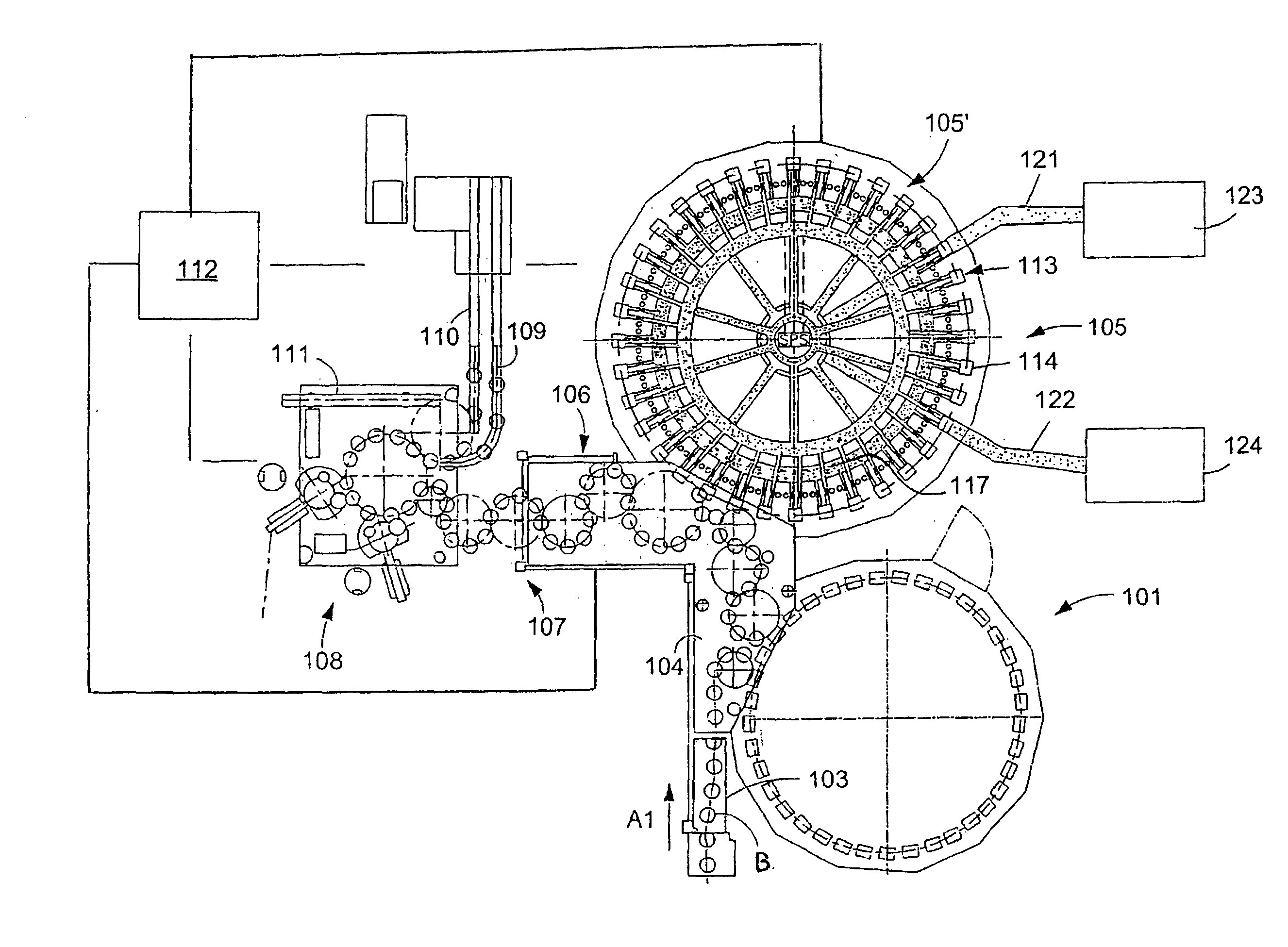
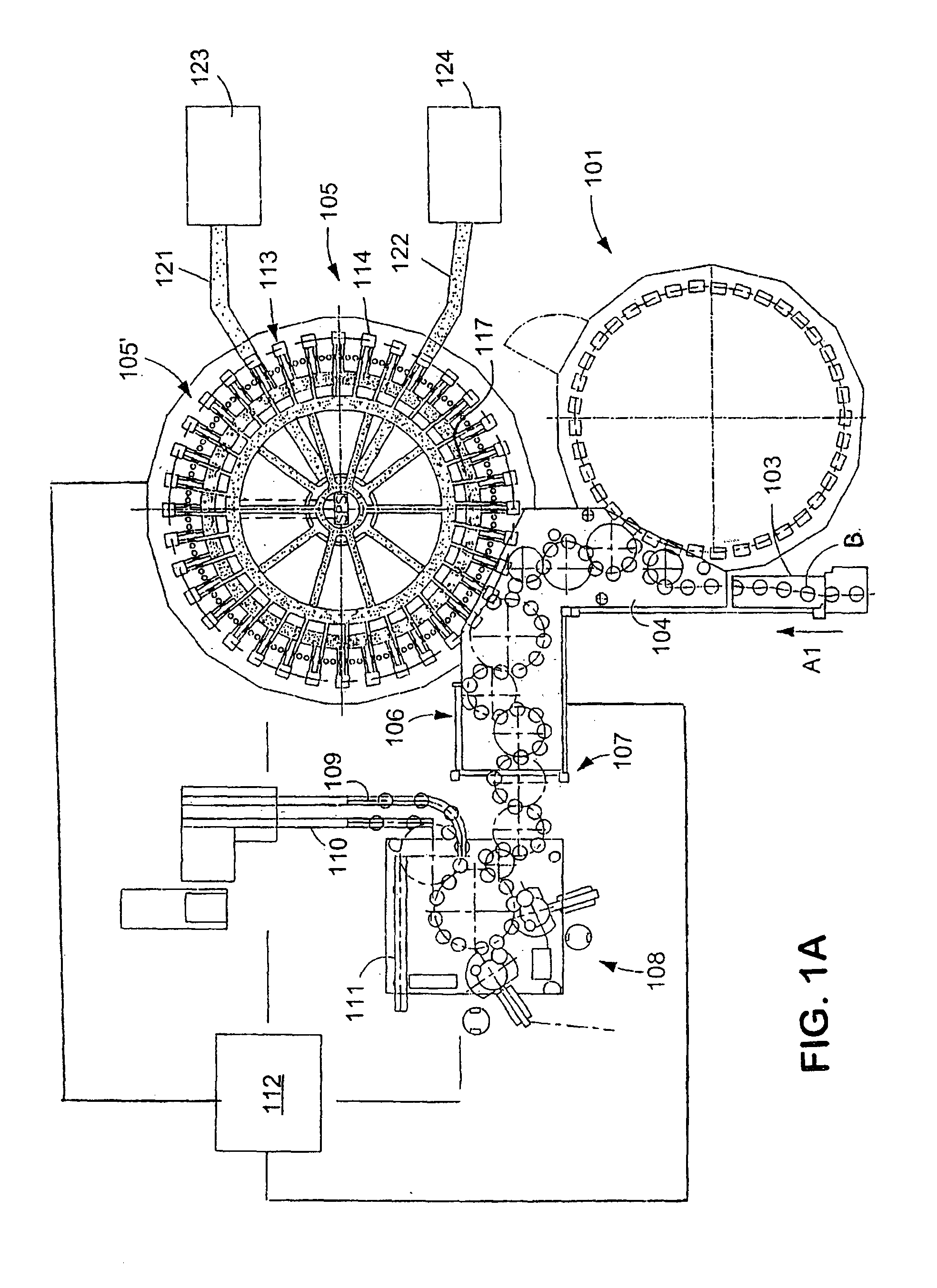
[0040]FIG. 1A shows schematically the main components of one possible embodiment example of a system for filling containers, specifically, a beverage bottling plant for filling bottles B with at least one liquid beverage, in accordance with at least one possible embodiment, in which system or plant could possibly be utilized at least one aspect, or several aspects, of the embodiments disclosed herein.

[0041]FIG. 1A shows a rinsing arrangement or rinsing stat...


PUM

PropertyMeasurementUnit
angleaaaaaaaaaa
angleaaaaaaaaaa
angleaaaaaaaaaa

Abstract

A beverage bottling plant for filling bottles with a liquid beverage material having a filling machine. The abstract of the disclosure is submitted herewith as required by 37 C.F.R. §1.72(b). As stated in 37 C.F.R. §1.72(b): A brief abstract of the technical disclosure in the specification must commence on a separate sheet, preferably following the claims, under the heading “Abstract of the Disclosure.” The purpose of the abstract is to enable the Patent and Trademark Office and the public generally to determine quickly from a cursory inspection the nature and gist of the technical disclosure. The abstract shall not be used for interpreting the scope of the claims. Therefore, any statements made relating to the abstract are not intended to limit the claims in any manner and should not be interpreted as limiting the claims in any manner.

Description

CONTINUING APPLICATION DATA[0001]This application is a Continuation of co-pending U.S. patent application Ser. No. 11 / 122,270, filed on May 4, 2005.BACKGROUND[0002]1. Technical Field[0003]The present application relates to a beverage bottling plant for filling bottles with a liquid beverage material having a filling machine for filling bottles, cans and similar containers as described herein below.[0004]2. Background Information[0005]A beverage bottling plant for filling bottles with a liquid beverage filling material can possibly comprise a beverage filling machine with a plurality of beverage filling positions, each beverage filling position having a beverage filling device for filling bottles with liquid beverage filling material. The filling devices may have an apparatus designed to introduce a predetermined volume of liquid beverage filling material into the interior of bottles to a substantially predetermined level of liquid beverage filling material. The apparatus designed to...

Claims


Application Information

Patent Timeline
Patent Type & Authority Applications(United States)
IPC IPC(8): B67C3/28B67C3/24B65B3/26B65B7/28B67C3/26
CPCB67C3/2614B67C2003/2677B67C2003/2645
Inventor KRULITSCH, DIETER-RUDOLF
Owner KHS GMBH
Learn More