Method and apparatus for applying a sheet to a substrate

a technology of substrate and method, applied in the field of method and apparatus for applying a sheet to a substrate, can solve the problems of complicated correction system, affecting the accuracy of the correction system, so as to achieve the effect of preventing the curvature of the contact front, reducing the risk of damage, and controlling the release ra

Active Publication Date: 2010-04-08
KONINKLIJKE PHILIPS ELECTRONICS NV
View PDF15 Cites 8 Cited by
  • Summary
  • Abstract
  • Description
  • Claims
  • Application Information

AI Technical Summary

Benefits of technology

[0020]An advantage is that shear components of these small forces, which are responsible for introducing stress within the substrate and / or sheet along the surfaces near the contact front, are thus small. Therewith distortion of the flexible sheet in the vicinity of the contact front is also minimized. Hence, at the moment of the actual establishment of the contact at the position of the contact front during the establishment of further contact, the sheet is substantially free of distortion with respect to its equilibrium state and therewith free of stress and deformation.
[0050]In an embodiment, the controlling means comprise restraining and releasing means for restraining and releasing at least a part of the second area of the second surface. The releasing means and restraining means advantageously allow to control the release rate. This in turn provides accurate control over stress and deformation during further contact establishment as described here before with regard to the method. Preferably the control of restraining and release means comprise actuators that operate in a contact less manner in order not to induce stress. Suitable actuators are (electro)magnetic units. Alternatively, nozzles for providing vacuum and an overpressure can be used. This has the advantage that the sheet o=r the substrate on which the actuators need to operate do not have to made of material that allow (electro)magnetic holding to be used. The actuators may be dispersed over the first area each of them acting on a different area of the sheet or substrate such that at least the entire relevant area can be controlled during the establishment of further contact.

Problems solved by technology

However, with the known methods and apparatuses the pattern gets distorted, since the stamp contacts the substrate in a deformed and stretched state.
In particular, it is noted that due to the elasticity and / or local strain of the flexible stamp, runout or a local deformation of the pattern may occur.
All in all, this solution requires a complicated correction system, and is far from practical.

Method used


Image

  • Method and apparatus for applying a sheet to a substrate
  • Method and apparatus for applying a sheet to a substrate
  • Method and apparatus for applying a sheet to a substrate

Examples


first embodiment

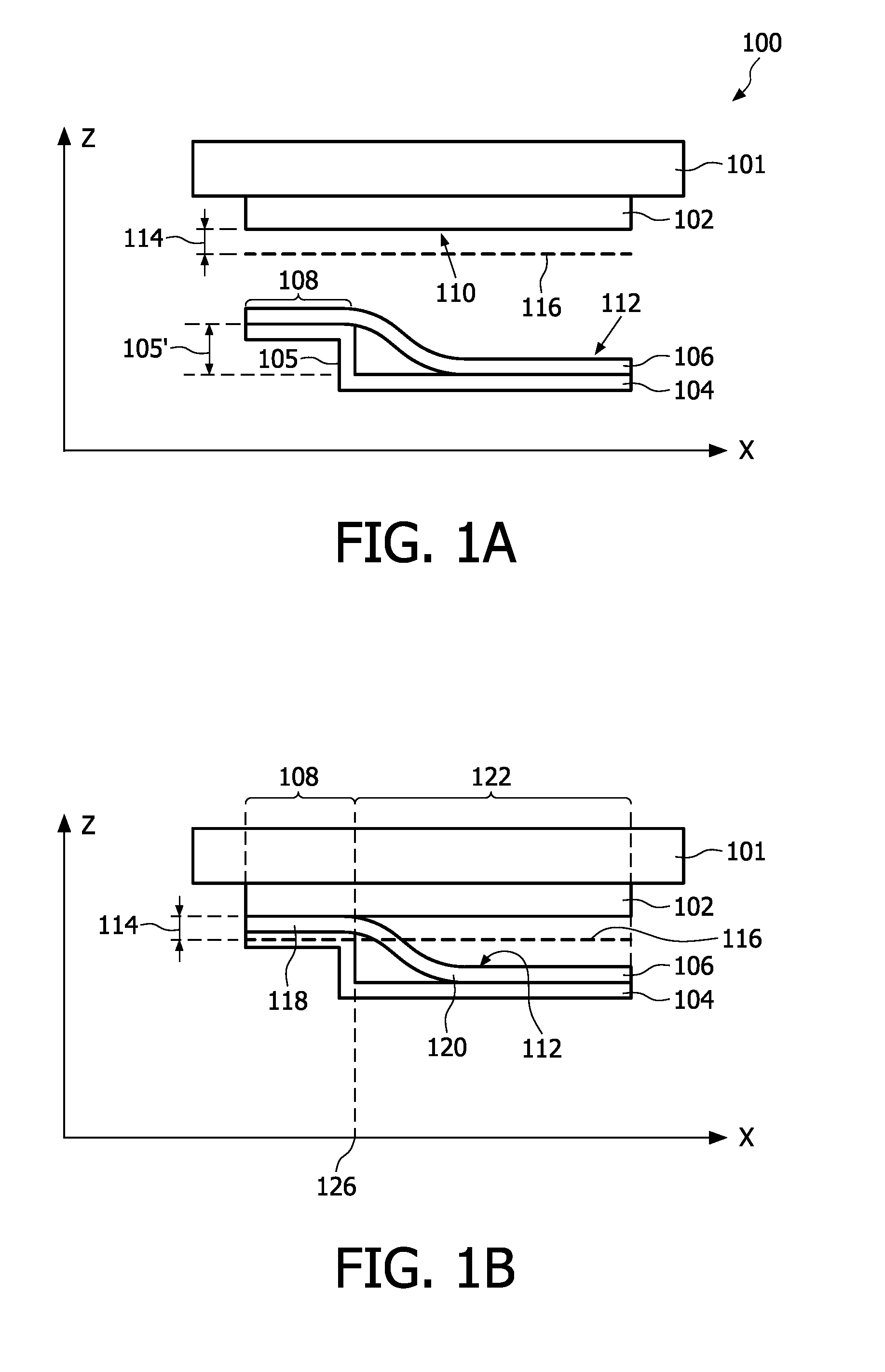
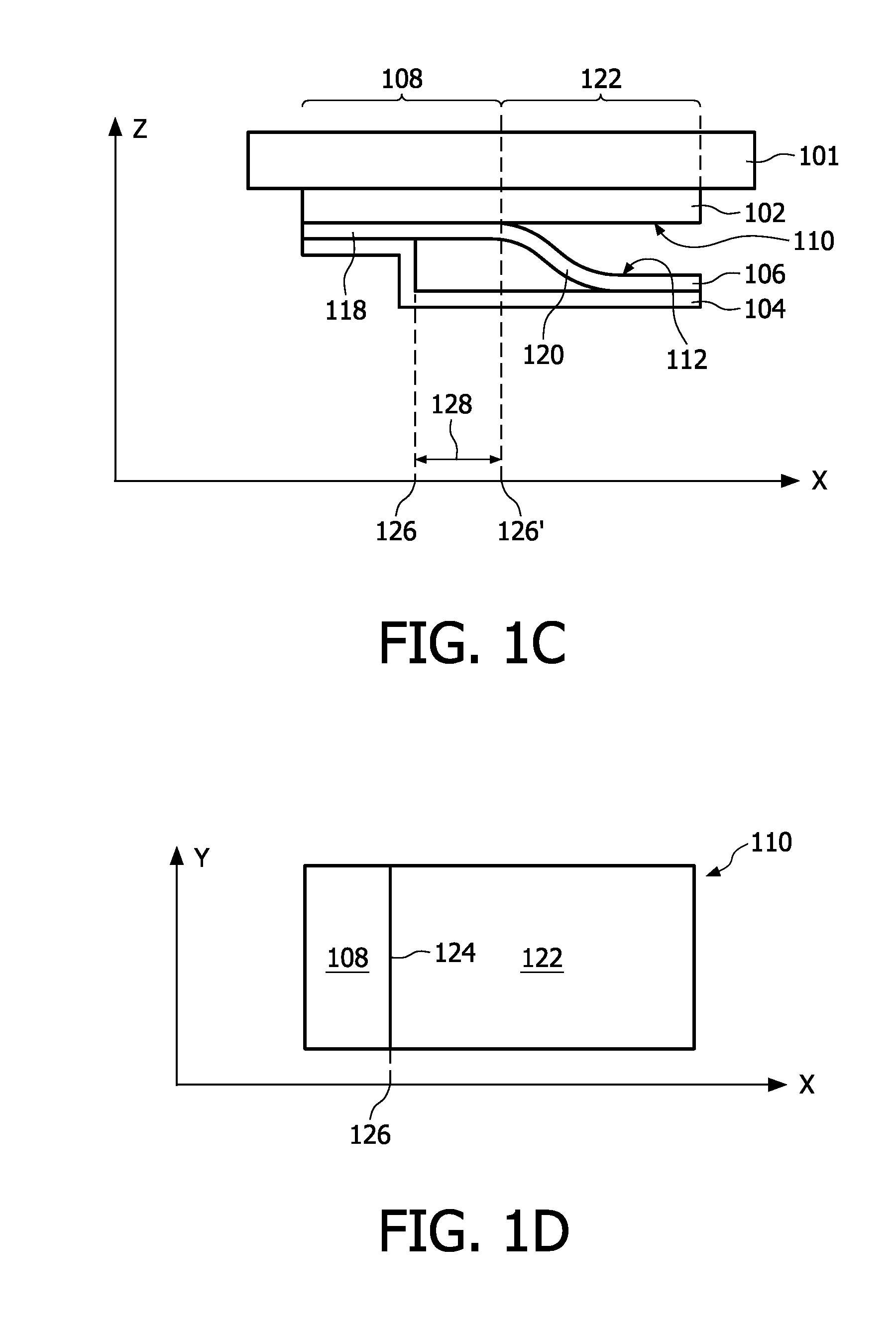
[0066]an apparatus and method according to the invention is described with reference to FIGS. 1A to 1F. The apparatus comprises a first holder 101 holding a substrate 102 for example by creating a vacuum in between the first holder 101 and the substrate 102 using vacuum nozzles (not shown) present in the first holder to create an under-pressure between the first holder and the substrate. This is for example common practice in semiconductor industry for handling and holding semiconductor wafers. Other mechanisms for holding the substrate using mechanical clamping or electromechanical attachment may be alternatively used.

[0067]The apparatus further comprises a second holder 104 having a shape such that it comprises a step 105 with a height 105′. The second holder 104 sustains a sheet 106, whereby in this embodiment the holder holds a first area 108 of the sheet firmly in for example the same manner as the substrate is held by the first holder. The sheet 106 is slightly bent due to the...

second embodiment

[0079]The method and apparatus for establishing further contact as used in a second embodiment may be advantageously used for counteracting the effects of advancement rates that vary over the first and second surfaces to be contacted with each other.

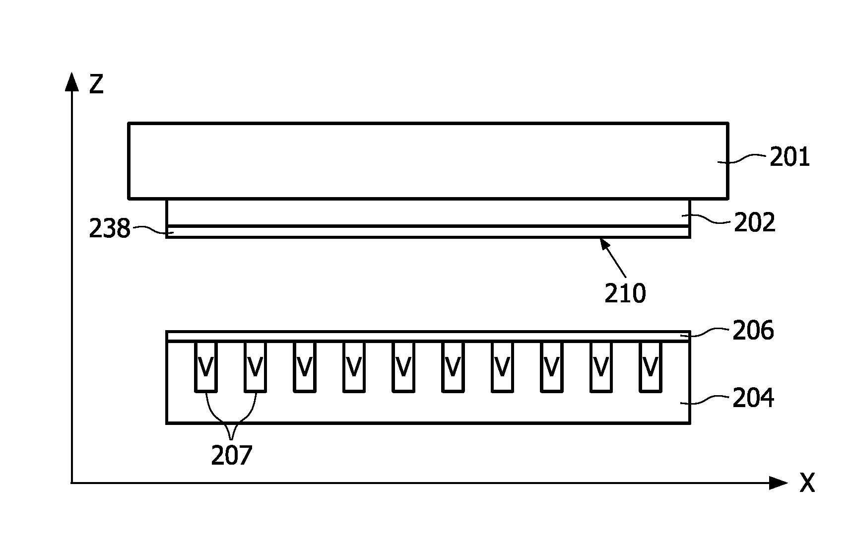
[0080]The second embodiment is described with respect to FIG. 2. This embodiment differs from the first embodiment in that after the establishment of the initial contact the second area is restrained from making further contact by attaching a portion of sheet to a second holder.

[0081]FIG. 2A shows a first holder 201 holding a substrate 202, the substrate having a first surface 210. Further shown is a second holder 204 having devices called actuators for restraining (holding) and releasing a sheet 206 held by the second holder 204. To this end the second holder 204 in this example comprises a plurality of spaced-apart pneumatic actuators 207. The apparatus also comprises means for controlling of the actuators in order to let them restrain...


PUM


Abstract

The invention provides a method and apparatus for laminating a sheet to a substrate in a stress free and distortion-less manner. The method comprises providing the sheet and substrate such that an attractive force between them exists that is capable of bringing the sheet and surface together at least when their distance is shorter than a critical distance. The method creates these conditions by locally making an initial contact between the sheet and substrate such that at a contact front, being the boundary between areas where the substrate and sheet are in contact and those where they are not in contact, these conditions exist. In a further step the sheet and substrate are allowed to gradually make contact such that the contact front advances along either of the substrate or sheet surface therewith increasing the contacting area between the substrate and the sheet. The method is advantages when used during imprint lithography or embossing processes or other processes where feature patterns need to be transferred from the substrate to the surface or vice versa.

Description

FIELD OF THE INVENTION[0001]The invention relates to a method for establishing contact between a first surface of a substrate and a second surface of a sheet. The invention also relates to a method for transferring a template pattern from the flexible sheet to the substrate using the method for establishing contact. The invention further relates to an apparatus for carrying out either of the methods.BACKGROUND OF THE INVENTION[0002]U.S. Pat. No. 5,669,303 discloses an apparatus for micro contact printing including a support structure, a flexible stamp having a stamping surface including a predetermined pattern disposed opposite the support structure, a pressure controlled chamber disposed above the support structure, and a mechanical attachment affixed to the flexible stamp. Furthermore, U.S. Pat. No. 5,669,303 discloses a method for micro contact printing. In the method, contact between a wetted stamping surface of a flexible stamp and the surface of an article is obtained by chang...

Claims


Application Information

Patent Timeline
Patent Type & Authority Applications(United States)
IPC IPC(8): B41F31/00
CPCB05C1/027B05D1/28G03F7/0002B82Y40/00B82Y10/00
Inventor VERSCHUUREN, MARCUS ANTONIUSMEGENS, MISCHA
Owner KONINKLIJKE PHILIPS ELECTRONICS NV
Why Eureka
Try Eureka