
Insert and package formed of an insert in a sleeve

a technology of insert and package, applied in the field of insert, can solve the problems of affecting the spring-back movement of the locking tab, increasing the size of the package in an undesired manner, and affecting the spring-back of both locking panels, so as to achieve the effect of improving the retention function

Pending Publication Date: 2010-04-08
STORA ENSO AB
View PDF7 Cites 1 Cited by
  • Summary
  • Abstract
  • Description
  • Claims
  • Application Information

AI Technical Summary

Benefits of technology

[0012]It is an object of the invention to provide an insert with an improved retaining functionality.
[0013]It is yet another object of the invention to provide a package, comprising a sleeve and an insert slidably received in the sleeve, with an improved retaining functionality.
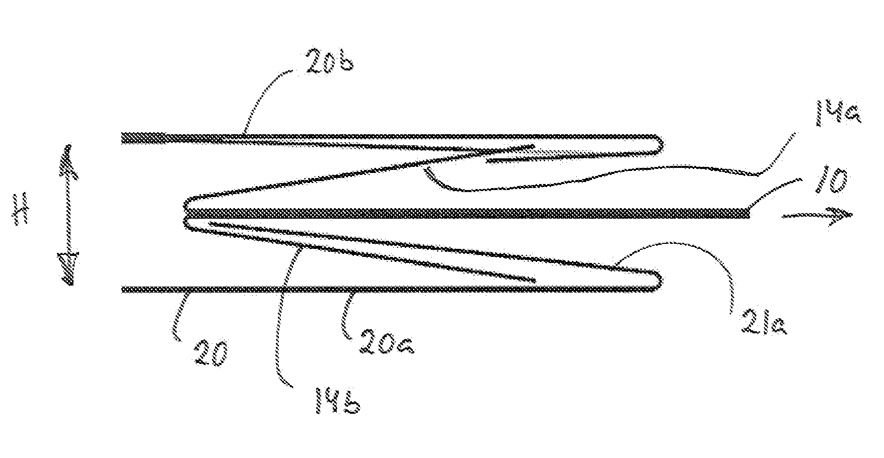
[0016]By providing the insert with two flap portions refoldable against both major surfaces of the insert a number of advantages is achieved compared to the prior art designs. Firstly it is possible achieve a centring effect by making the two flap portions slide against opposite inside walls of the compartment formed by the sleeve. Secondly, by arranging the flap portions in the vicinity of each other or directly opposite each other on the insert, i.e. at about or at the same location when viewed in the direction in which the insert is slidable in the sleeve, it is possible to make the flap portions help each other. If one of the flap portions has lost some of its spring-back ability, the other flap portion will urge the insert and the one flap portion towards its retaining mechanism. Thus, not only will the addition of a second retaining mechanism add the security of locking even if the first locking mechanism failure, it will additionally increase the likelihood of the first retaining mechanism as such to lock properly. Thirdly, it is beneficial to have oppositely extending flap portions if one of the flap portions is used both for release from an initial locking mechanism and for preventing complete removal, i.e. forming part of an retaining mechanism. In such a case the flap portion that has been maneuvered repeatedly every time the user has slid the insert partly out of the sleeve is likely to have weakened and lost at least some of its spring-back ability whereas the opposite flap portion has remained unaffected during this normal use and will both securely lock into its retaining mechanism and if arranged opposite the weak flap portion also help the weak flap portion securely lock into its retaining mechanism. Fourthly, by having oppositely extending flap portions it is also possible to make specific use of the fact that many laminated materials, such as paper based materials laminated with one or more polymer layers, are often not symmetrical and has a tendency to have a greater bending stiffness in one direction compared to the other. By balancing the use of different layers of different polymers and / or different layer thicknesses and / or different degrees of orientation of the polymers in the layers it is possible to optimise the sleeve for allowing repeated bending in one direction without loosing spring-back too much and for being strong in the other direction.
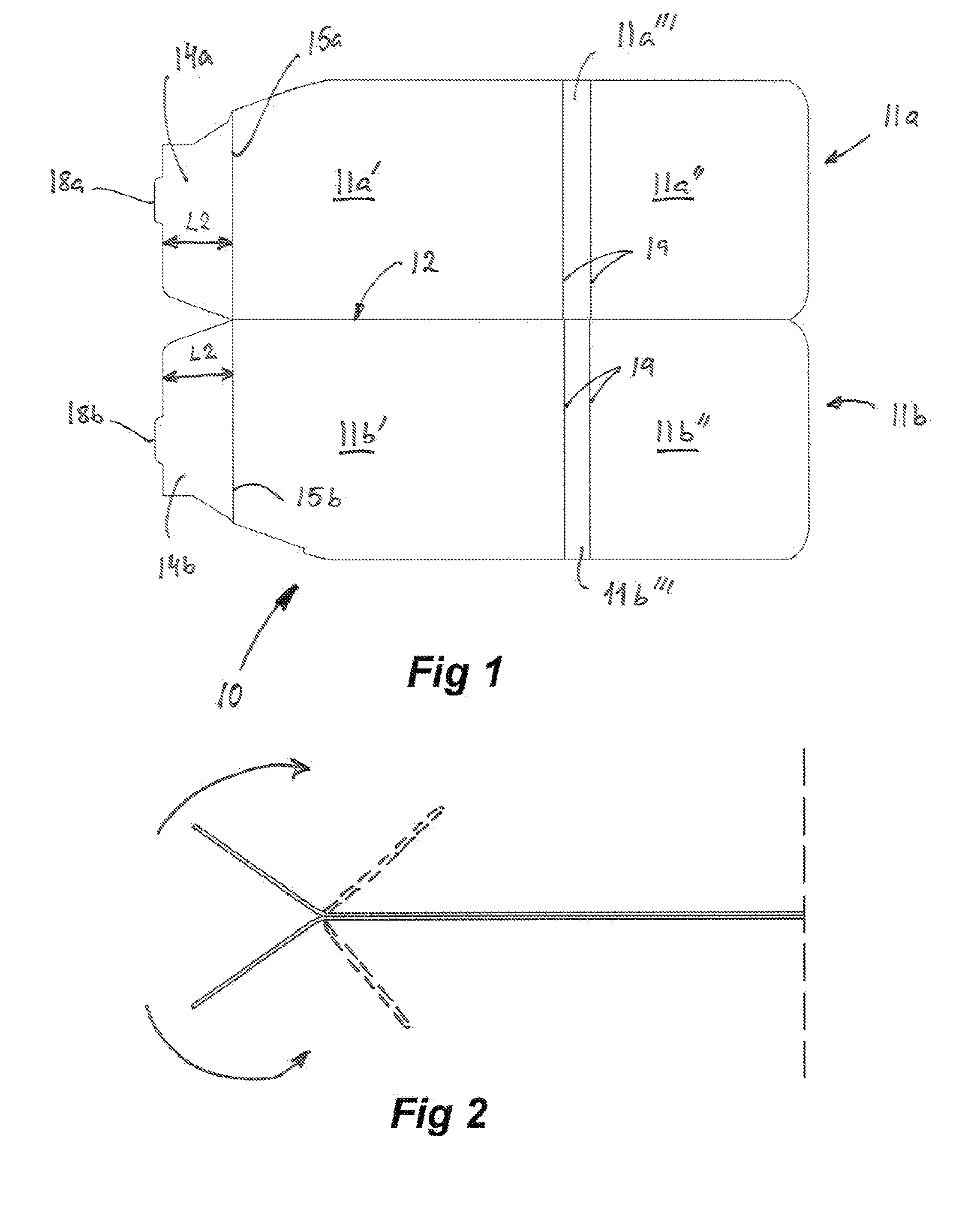
[0020]The base portion may comprise two portions refolded against each other about a fold line extending essentially along the direction in which the insert is adapted to be slidable when received in a sleeve. Such a design is especially suitable to use for so-called blister packs. A blister pack has often different bending strength in different directions. By refolding the base portion along a longitudinal line (extending along the sliding direction) both flap portions will be folded in the same direction from a material layer view point when they are refolded against the opposite major surfaces of the refolded base portion. Thereby it is possible to fold both flap portions in the from a material layer view point optimum direction, thereby achieving the optimum spring-back properties for both flap portions. Moreover, the refolding also makes it possible to fold a blister pack such that the blisters of the two portions are tucked in the flat areas between the blisters of the opposing portions.
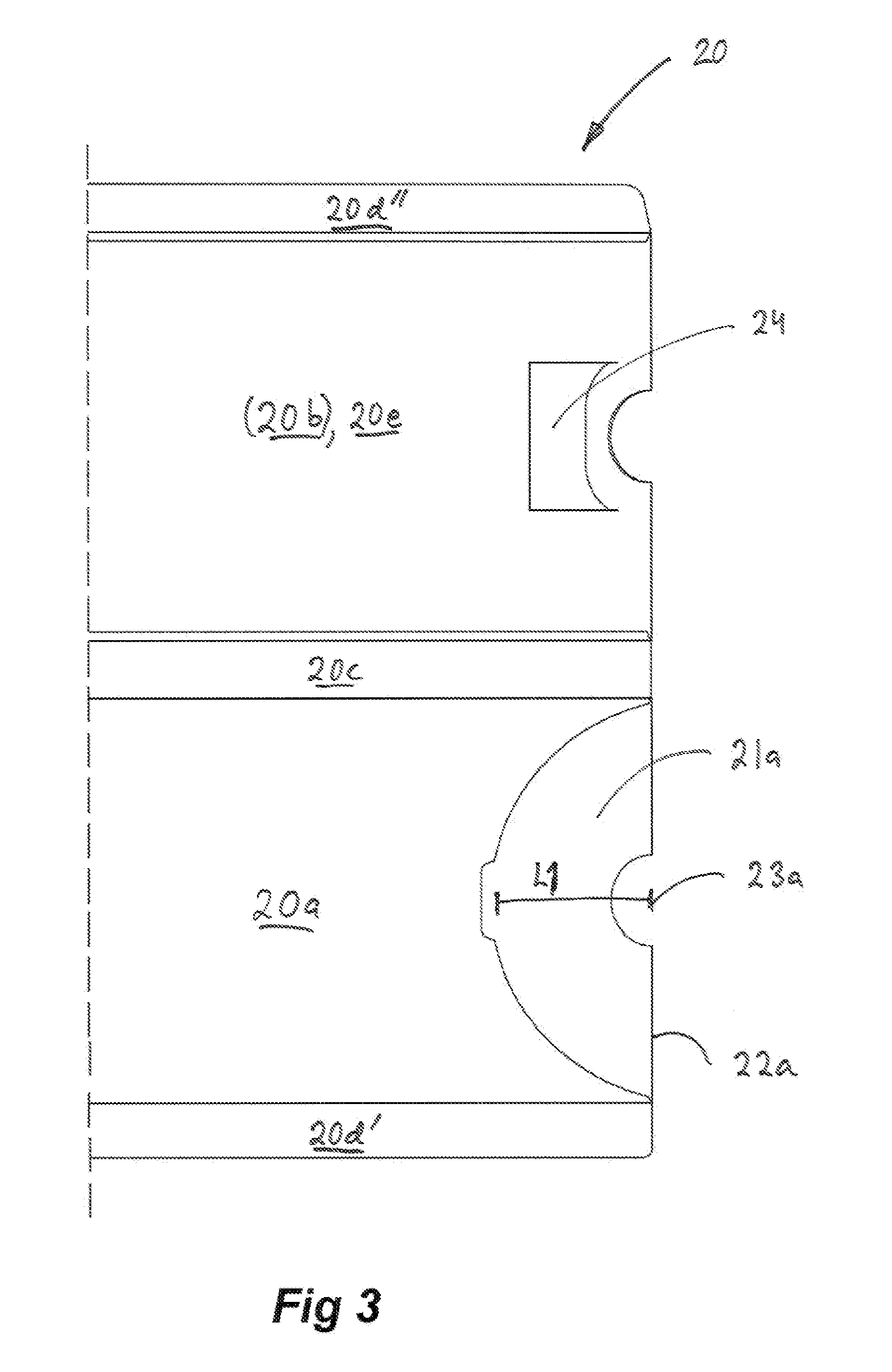
[0028]In accordance with one embodiment the sleeve is provided with one panel of the compartment having an through-going opening close to the inner end of the compartment and a refolded flap close to the opening of the compartment, whereas the other panel, opposing the one panel, also having a refolded flap close to the opening of the compartment. With this design a first flap portion of the insert may be used for selectively releasing the insert from being moved at all by releasably locking into the through-going opening, whereas both the first and second flap portions of the insert may prevent complete removal by interacting with the refolded flaps on both sides of the opening thereby forming part of said retaining means.

Problems solved by technology

Both the prior art packages above is associated with a problem related to the design of the locking mechanisms.
However, the thickness of the locking chamber is also a thickness of the package that cannot be used to contain the products, thereby increasing the size of the package in an undesired manner.
This will negatively effect the spring-back movement of this locking tab.
When the user tries to completely remove the slide card from the package, the design of the package relies on the spring-back of the two locking panels, but as discussed above the spring-back of both locking panels is negatively affected by the previous use of the package.
Although improved over EP 1 002 744 A1 and U.S. Pat. No. 6,491,211 B1 also the package of WO2006 / 068602 A1 may encounter situations where the spring-back movement of the second locking flaps does not offer the desired degree of security against removal of the insert from the sleeve.

Method used


Image

  • Insert and package formed of an insert in a sleeve
  • Insert and package formed of an insert in a sleeve
  • Insert and package formed of an insert in a sleeve

Examples


Embodiment Construction

[0039]With reference to FIG. 1, the insert 10 comprises a base portion 11 formed of two portions 11a-b foldable towards each other along a fold line 12. The fold line 12 extends in the longitudinal direction; in the direction along which the insert 10 is slidable when received in a sleeve. The two portions 11a-b are in turn each formed of two portions 11a′, 11a″ and 11b′, 11b″ foldable along a set of fold lines 19 defining a small panel 11a″′, 11b″′ between the different portions of the base portion 11. The two portions 11a-b forming the base portion 11 may be provided with numerous blisters (not shown) containing unit dose products, such as medicine or the like. The insert 10 is further provided with two flap portions 14a-b foldably connected to the two portions 11a-b forming the base portion 11, respectively, via two fold lines 15a-b. The two flap portions 14a-b extend in the imaginary extension of respective portion 11a-b forming the base portion 11. The two fold lines 15a-b exte...


PUM


Abstract

The disclosure relates to an insert adapted to be slidably received in a sleeve. The insert comprises a base portion, a first flap portion adapted to be refolded about a first fold line, a second flap portion adapted to be refolded about a second fold line, wherein the second fold line extends essentially in parallel with the first fold line, and wherein the first flap portion is refolded in relation to the base portion such that it extends backwardly over a first surface of the base portion, and the second flap portion is refolded in relation to the base portion such that it extends backwardly over a second surface, opposite the first surface, of the base portion. The disclosure also relates to a sleeve adapted to slidably receive such an insert and the thus formed package.

Description

FIELD OF INVENTION[0001]The present invention relates to an insert adapted to be slidably inserted in a sleeve. The insert is provided with a base portion, a first flap portion adapted to be refolded about a first fold line, and a second flap portion adapted to be refolded about a second fold line. The present invention also relates to a package formed of a sleeve and a within the sleeve slidably received insert.[0002]The present invention is especially suitable for, but not limited to, controlled easy-access package for child resistant, senior-friendly storage of unit dose products or the like, carried by an insert.TECHNICAL BACKGROUND[0003]U.S. Pat. No. 6,491,211 B1 discloses a child resistant carton assembly comprising a package and a tray slidably receivable within the package. The package comprises a top panel and a locking panel arranged in parallel with and at a distance from the top panel, thereby forming a locking chamber together with the top panel. The tray includes a loc...

Claims


Application Information

Patent Timeline
IPC IPC(8): B65D90/00B32B5/00
CPCB65D5/38Y10T428/24215B65D2215/02B65D83/0463
Inventor DEHLIN, MARCUS
Owner STORA ENSO AB
Learn More