Discharge device

a discharge device and discharge technology, applied in the direction of liquid handling, applications, instruments, etc., can solve the problems of a number of difficulties in the discharge device of the prior art, and have not been completely solved

Active Publication Date: 2010-04-08
APTAR RADOLFZELL
View PDF12 Cites 19 Cited by
  • Summary
  • Abstract
  • Description
  • Claims
  • Application Information

AI Technical Summary

Benefits of technology

[0012]It is particularly advantageous if use can be made of both the stroke movement and the return stroke movement of the operating member by means of a suitable operative coupling in order to bring about the displacement of the locking member. Both during the stroke movement and during the return stroke movement energy is fed into the first spring means. Through this use of both movements of the operating member relative to the housing, an advantageous transmission can be obtained, so that the tensioning of the spring means taking place simultaneously with the movement of the operating member requires no significantly increased operating force on the part of the user.
[0054]Said detent means are arranged in such a way that the second component of the detent means which is disposed fixedly relative to the operating member, is capable of trespassing the first component only in the stroke direction, but not in the return stroke direction. Thus, during a stroke movement the second component of the detent means, e.g. a snap member deflectable in a radial direction, is directed along the first component, e.g. a step, and is thereby intermittently deflected. As soon as said first component of the detent means has been overridden by the second component, any return to the starting position is inhibited without an intermediate reaching of the end position of the operating member. The configuration having detent means is simple to manufacture and particularly cost effective. As said second component of the detent means, cams may be provided which may be identical to the above described cams for engagement of the connecting link groove or may be disposed in an offset position relative to the latter. The first component of the detent means, as e.g. a step, may be disposed in the vicinity of such a connecting link groove or separate from the connecting link groove.

Problems solved by technology

The prior art discharge devices suffer from a number of difficulties and disadvantages.
These are the restoring or maintaining of the locked position in the case of a power supply failure, the problem of the high energy requirements in general terms and the prevention of operation in the case of an unusual operating direction and the prior art has still not been able to completely solve these problems.

Method used


Image

  • Discharge device
  • Discharge device
  • Discharge device

Examples


second embodiment

[0106]In the locked state of FIG. 8a an operation of the discharge device is impossible for the reasons given in connection with the embodiment of FIGS. 1 to 5. On pressing down the operating member 188, the cams of the operating member 188 not shown in conjunction with this second embodiment would be prevented by the locking sections of locking member 152 from a displacement necessary for a discharge process.

[0107]Only on energizing electromagnet 147 through the not shown control electronics is it possible to bring about the release state of the discharge device. Energization of electromagnet 147 leads to a brief force actuation of the bolt auxiliary member 144 to the right in direction 5b. The force actuation by electromagnet 147 need not be very powerful, because it only needs together with the force actuation by the spring clip 148 on the bolt auxiliary member 144 to overcome the holding force in the opposite direction provided by permanent magnet 146. The displacement of the bo...

first embodiment

[0108]The state of FIG. 8b represents the resulting release state of the discharge device. Through the displacement of the push rod component 178 there has also been a rotation of locking member 152 in direction 2b, so that said locking member 152 is now in a position in which the cams of operating member 188 can be moved past the locking sections of locking member 152 so as to enable a discharge process. This corresponds to the state of FIGS. 3a to 3c of the

[0109]As has already been described relative to the first embodiment, the discharge process within the scope of the stroke and return stroke movements once again leads to a rotation of locking member 152 in the direction of arrow 2a. As a result of the forcible coupling of locking member 152 with push rod component 178 the latter is also moved in the direction of arrow 6b. In a first partial portion said movement initially has no consequences regarding the position of bolt 142. Only when locking cam 175 has come into the vicinit...


PUM


Abstract

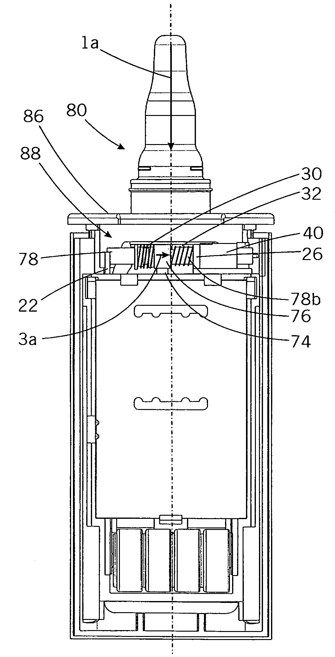
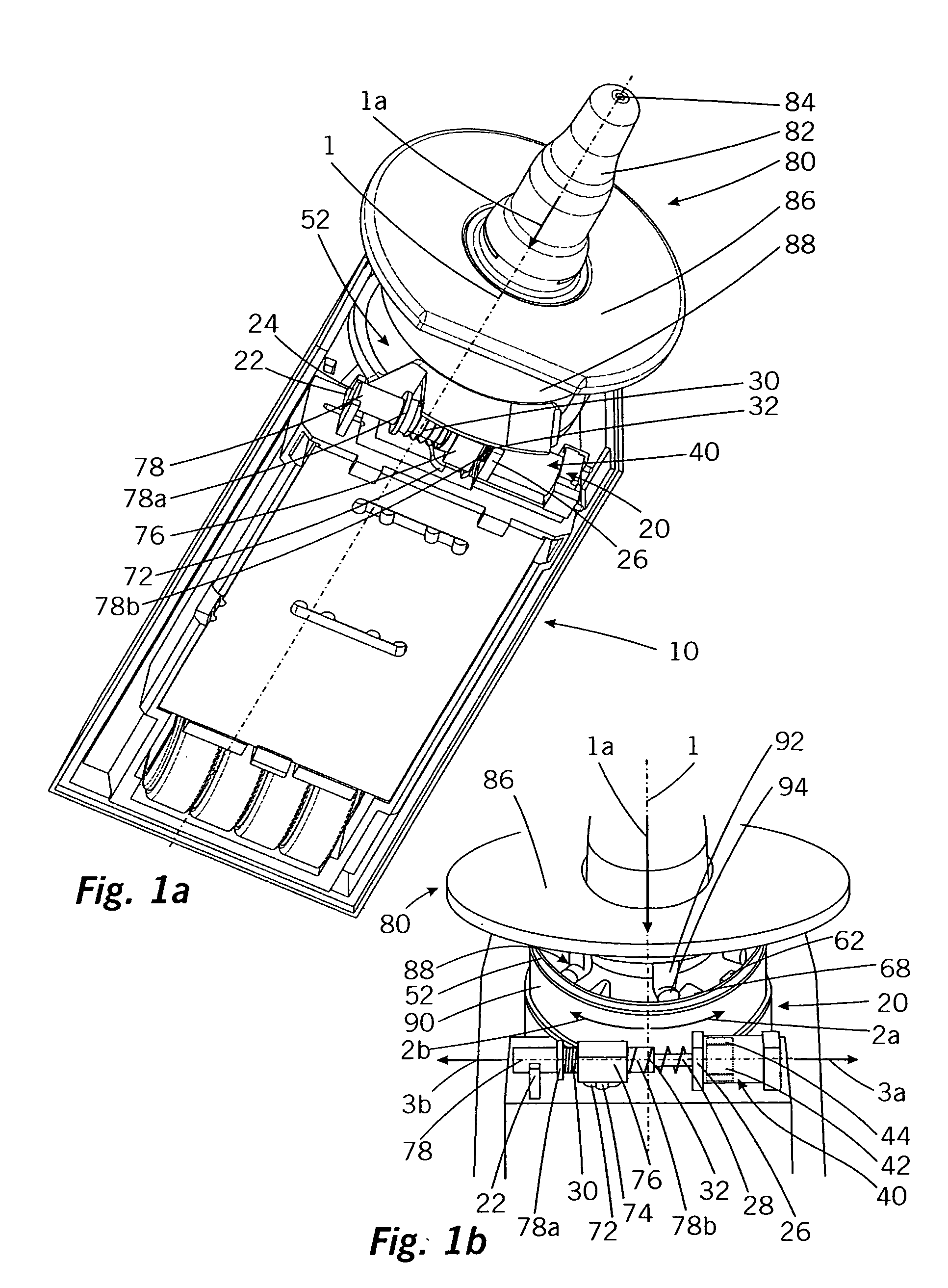
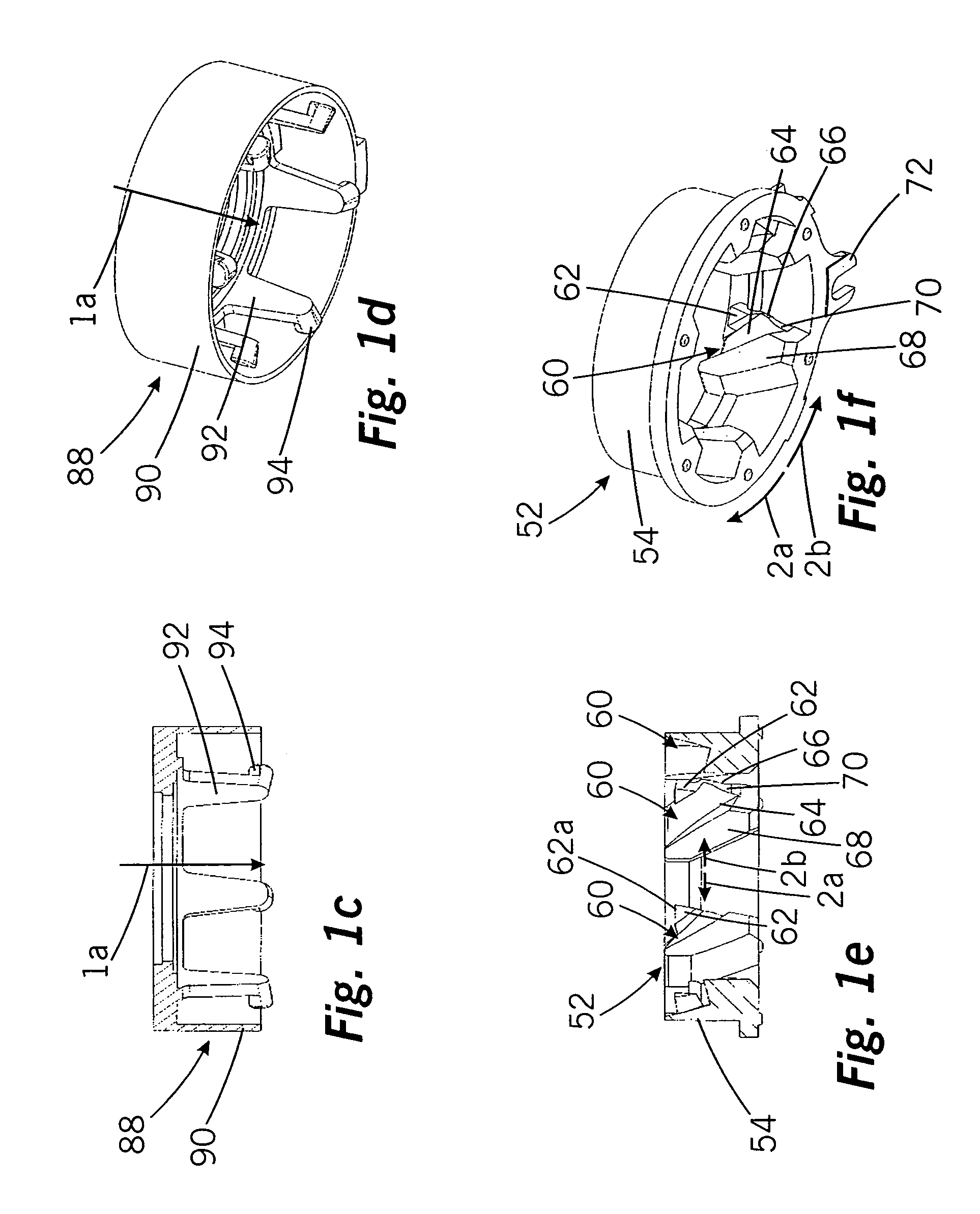
A discharge device for media has a housing (10), an operating member (88) manually movable relative to the housing (10) and which, for performing a discharge can be transferred from an unoperated starting position in the direction of an operating direction (1a) into an operated end position and with a locking member (52), which is displaceable relative to the housing (10) between a locked position where it prevents the displacement of the operating member (88) into the end position and a release position in which it permits the displacement of the operating member (88) into the end position.

Description

FIELD OF APPLICATION AND PRIOR ART[0001]The invention relates to a discharge device for media having a housing, an operating member manually movable relative to the housing and which for the operation of a discharge means can be transferred from an unoperated starting position in the operating direction into an operated end position, and a locking member, which is displaceable relative to the housing between a locked position in which it prevents the displacement of the operating member into the end position and a release position in which it allows the displacement of the operating member into the end position.[0002]Such discharge devices are known from the prior part. They are used for the discharge of in particular pharmaceutical media, such as e.g. liquid medicaments. Such discharge devices have a housing in which is provided a discharge means, e.g. a piston pump, which in reaction to a manual movement of the operating member delivers the medium from a medium reservoir to a disc...

Claims


Application Information

Patent Timeline
Patent Type & Authority Applications(United States)
IPC IPC(8): B67D5/08
CPCA61M15/0065A61M15/08B05B11/3059B05B11/3018A61M2205/276B05B11/1018B05B11/1059
Inventor CATER, MIROKOERNER, JOACHIMUMBEER, VOLKERFUCHS, KARL-HEINZ
Owner APTAR RADOLFZELL
Why Eureka
Try Eureka