Low Voltage Outdoor Lighting Power Source and Control System

a low-voltage outdoor lighting and power source technology, applied in the field of outdoor lighting systems, can solve the problems of short life of outdoor landscape lighting systems, frequent replacement, and low efficiency of bulbs, and achieve the effect of efficient conversion

Active Publication Date: 2010-04-08
HUNTER INDUSTRIES
View PDF19 Cites 61 Cited by
  • Summary
  • Abstract
  • Description
  • Claims
  • Application Information

AI Technical Summary

Benefits of technology

[0011]The present invention provides a power source and control system that is particularly suited for use in an outdoor landscape lighting system. The power source and control system includes at least one switching mode AC-to-DC power supply having an additional output stage for efficiently converting the DC output signal into another relatively low fre

Problems solved by technology

These bulbs are not very efficient because they generate significant heat.
There are other well-known problems with incandescent bulbs.
They often have a short life in outdoor landscape lighting systems and therefore need frequent replacement.
Incandescent bulbs can only achieve different colors using shaded lenses.
This allows the simple unprotected burial of the output wiring from these transformers at no particular depth without creating a safety hazard.
While fairly safe, conventional outdoor lighting power supplies are bulky, heavy, and not very efficient.
All transformers have losses resulting in efficiencies l

Method used


Image

  • Low Voltage Outdoor Lighting Power Source and Control System
  • Low Voltage Outdoor Lighting Power Source and Control System
  • Low Voltage Outdoor Lighting Power Source and Control System

Examples


second embodiment

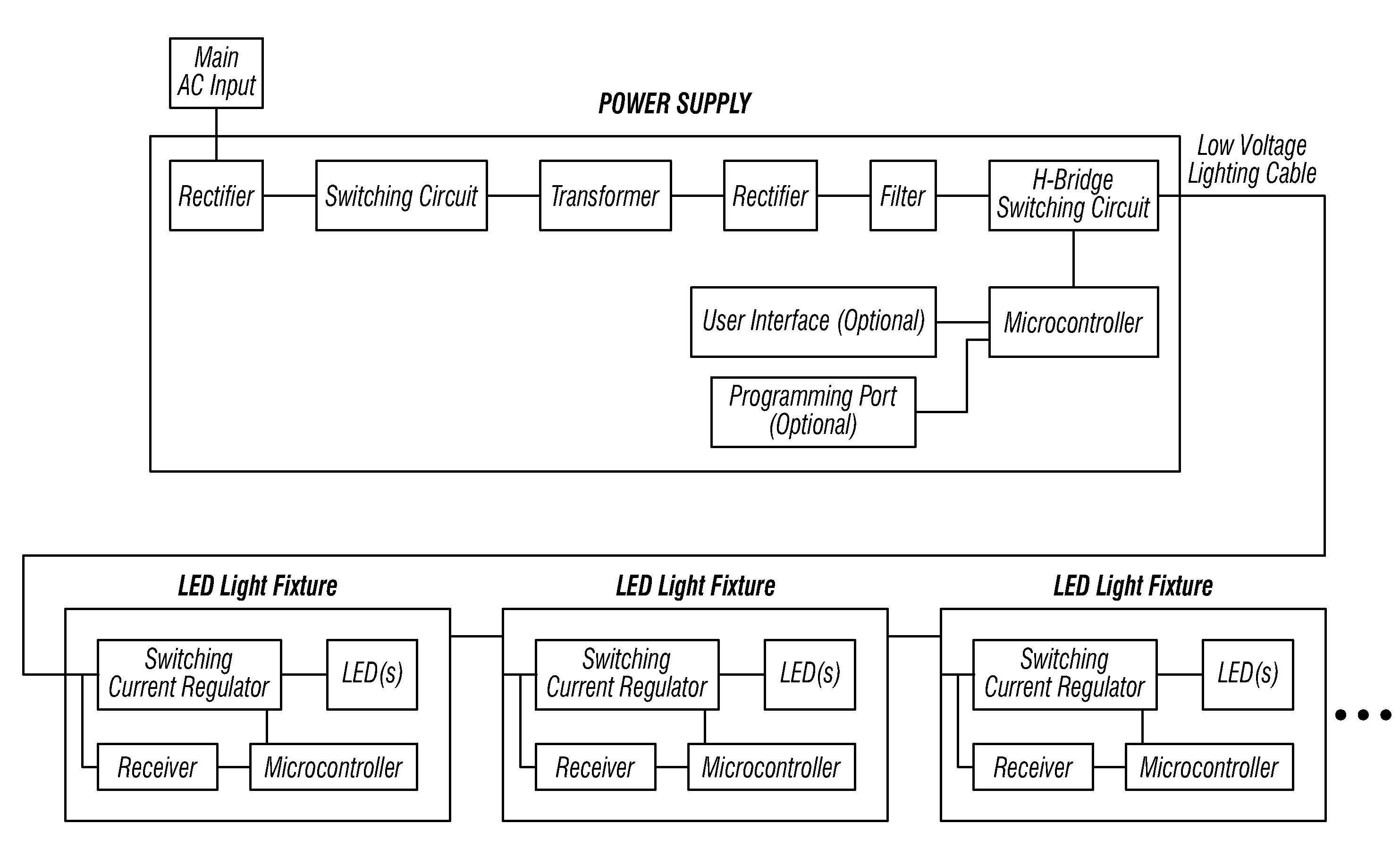
[0042]FIG. 7 is a block diagram illustrating the system of the present invention. The second embodiment uses a single switch mode power supply, and what is commonly known as an H-bridge to switch opposite polarity signals to the field wiring. The H-Bridge consists of four electronic switches (MOSFETs) that allow either of the power supply leads to be connected to either of the output wires. FIG. 8 is a flowchart of the controller timing, FIG. 9A and FIG. 9B illustrate signal waveforms for the gates of the MOSFETs and FIG. 10A and FIG. 10B illustrate signal waveforms for the drains of the MOSFETs and the composite output of the embodiment of FIG. 7. The output waveform on the field wiring is identical to that of the first embodiment of FIG. 3, although the mechanism for producing that waveform is different.

[0043]The operation of the second embodiment of FIG. 7 may be better understood by considering the operation as having four distinct timing phases. During phase 1, MOSFETS Q1 and Q...


PUM


Abstract

A power source and control system is particularly suited for use in an outdoor landscape lighting system. The power source and control system includes at least one switching mode AC-to-DC power supply having an additional output stage for efficiently converting the DC output signal into another relatively low frequency AC signal for transmission to a plurality of buried power conductors. A Manchester encoded control signal is encoded at a relatively high frequency onto the AC signal sent over the buried power conductors so that intelligent LED lighting fixtures can be powered by the AC signal and selectively have their intensity changed when they decode the control signal.

Description

CROSS-REFERENCES TO RELATED APPLICATIONS[0001]This application is filed pursuant to 37 C.F.R. 1.53(b) and claims the benefit under 35 U.S.C. §119(e) of U.S. Provisional Application No. 61 / 102,261 filed Oct. 2, 2008 entitled “Low Voltage Outdoor Lighting Power Source / System” and U.S. Provisional Application No. 61 / 218,883 filed Jun. 19, 2009 entitled “Intelligent Landscape Light with Embedded Decoder.”BACKGROUND OF THE INVENTION[0002]1. Field of the Invention[0003]This invention relates generally to outdoor lighting systems and more particularly to a power source and control system suitable for supplying power to present or next generation outdoor lighting fixtures.[0004]2. Description of the Related Art[0005]Outdoor lighting is popular for security, aesthetic, safety, and other reasons. Energy efficient power sources are desirable, and required by law for certain applications in certain areas.[0006]Until recently, outdoor lighting fixtures housed, almost exclusively, 12V incandescen...

Claims


Application Information

Patent Timeline
IPC IPC(8): H05B37/02
CPCH05B33/0842Y02B20/72Y02B20/48H05B37/0263H05B47/185Y02B20/40H05B45/39H05B45/3725H05B45/375
Inventor WOYTOWITZ, PETER J.
Owner HUNTER INDUSTRIES
Why Eureka
Try Eureka