Device for generating light with a variable color

Inactive Publication Date: 2010-04-08
PHILIPS HLDG LIGHTING BV
View PDF11 Cites 42 Cited by
  • Summary
  • Abstract
  • Description
  • Claims
  • Application Information

AI Technical Summary

Benefits of technology

[0012]According to an important aspect of the present invention, a two-dimensional color table is defined, effectively mapping the upper surfaces of the three-dimensional color space. The two coordinates of the color points in the table are hue and saturation. Color points having the same hue are defined such that the intervals between successive color points are substantially equal, as measured in a perceptually uniform color space, for instance the L*a*b* space. As a result, when stepping from one color point to the next along a line of constant hue, a user will perceive equal changes in saturation. Along the boundary of the color space (i.e. maximum saturation), between the primary colors, certain specific intermediate color points are predefined such as to make sure that those specific colors can be produced by the system. Between two neighboring primary colors, there is always defined at least one specific int

Problems solved by technology

A problem is that the RGB color space is not a linear space, so that, when taking a discrete step of a certain size along one of the color intensity coordinate axes, the amount of color change perceived

Method used


Image

  • Device for generating light with a variable color
  • Device for generating light with a variable color
  • Device for generating light with a variable color

Examples


Example

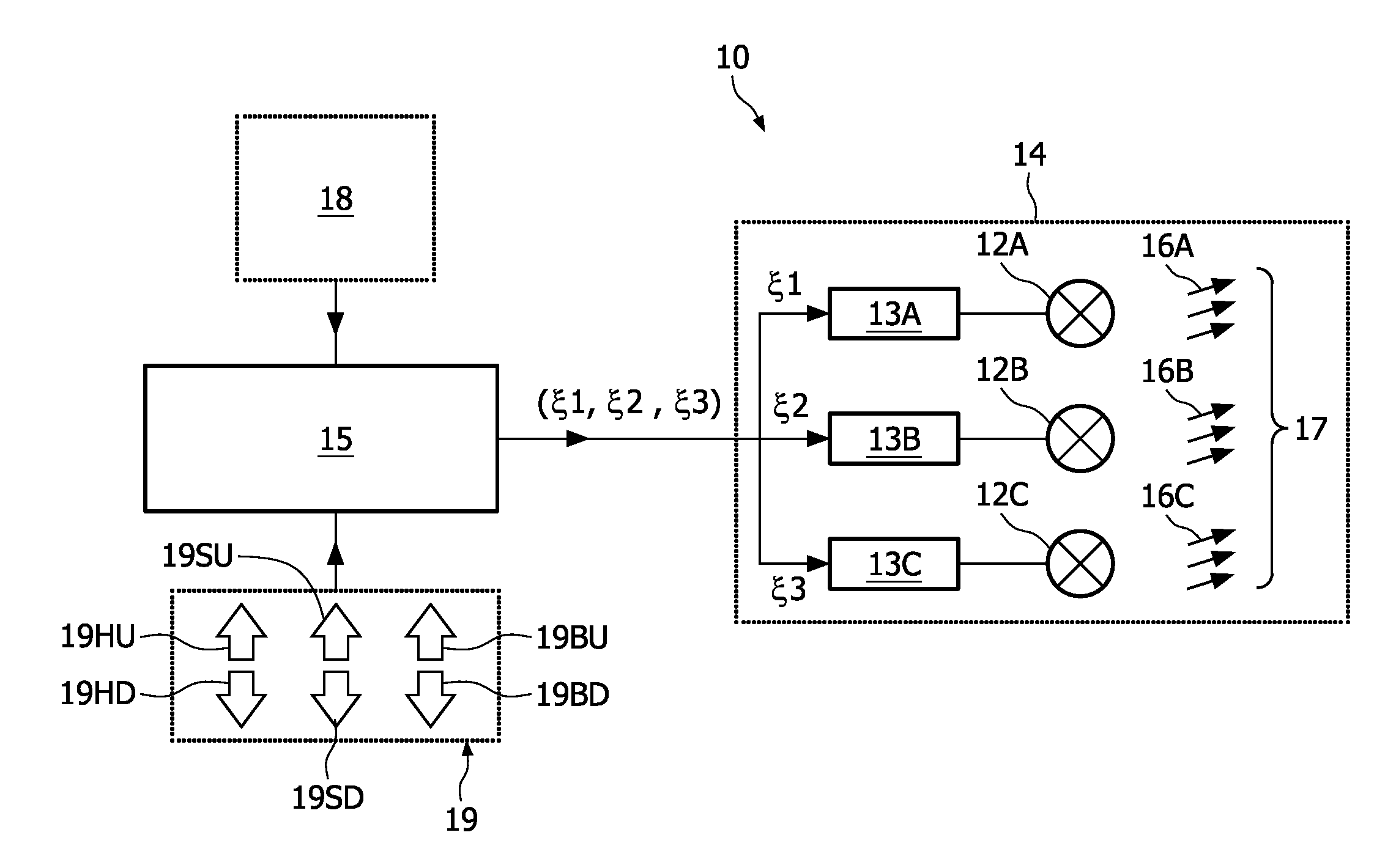
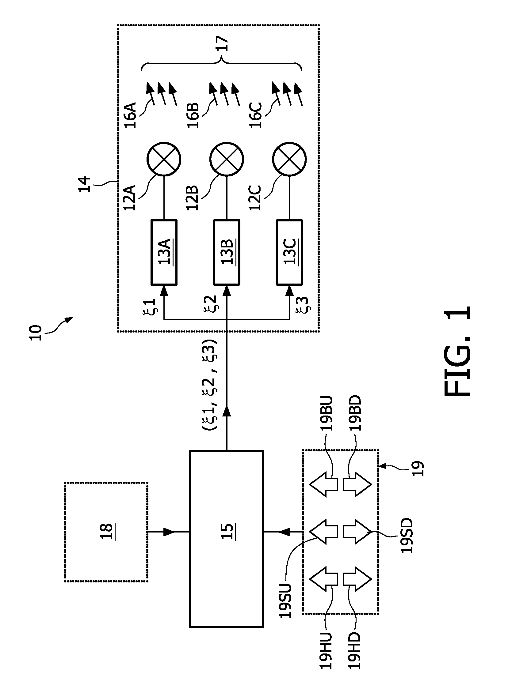
[0019]FIG. 1 schematically shows a block diagram of an illumination system 10, comprising a lamp assembly 14. The lamp assembly 14 comprises a plurality (here: three) of lamps 12A, 12B, 12C, for instance LEDs, each with an associated lamp driver 13A, 13B, 13C, respectively, controlled by a common controller 15. A user input device is indicated at 19. The three lamps 12A, 12B, 12C generate light 16A, 16B, 16C, respectively, with mutually different light colors; typical colors used are red (R), green (G), blue (B). Instead of pure red, green and blue, the lamps will typically emit light close-to-red, close-to-green and close-to-blue. The overall light emitted by the lamp assembly 14 is indicated at 17; this overall light 17, which is a mixture of individual lights 16A, 16B, 16C, has a color determined by the mutual light intensities LI(R), LI(G), LI(B) of the primary lamps 12A, 12B, 12C, which in turn are determined by control signals ξ1, ξ2, ξ3 generated by the controller 15 for the ...


PUM


Abstract

In an illumination system (10), comprising: a lamp assembly (14) with a plurality of lamps (12A, 12B, 12C) and associated lamp drivers (13 A, 13B, 13C); a common controller (15) for generating control signals (ξ1, ξ2, ξ3) for the lamp drivers (13A, 13B, 13C); a memory (18) containing a color table with color points; the color points of the color table are located in a two-dimensional plane corresponding to a ceiling of a color space. Perimeter color points (PC) are located on the borderline of said plane, in groups of equidistant color points, as measured in a perceptual uniform second color space. Equidistant spoke color points (SC) are located on constant hue lines (42) in said plane, constant hue line connecting one of said perimeter color points (PC) to a white point (W).

Description

FIELD OF THE INVENTION[0001]The present invention relates in general to the field of lighting. More particularly, the present invention relates to an illumination device for generating light with a variable color.BACKGROUND OF THE INVENTION[0002]Illumination systems for illuminating a space with a variable color are generally known. Generally, such systems comprise a plurality of light sources, each light source emitting light with a specific color, the respective colors of the different light sources being mutually different. The overall light generated by the system as a whole is then a mixture of the light emitted by the several light sources. By changing the relative intensities of the different light sources, the color of the overall light mixture can be changed.[0003]It is noted that the light sources can be of different type, such as for instance TL lamp, halogen lamp, LED, etc. In the following, simply the word “lamp” will be used, but this is not intended to exclude LEDs.[0...

Claims


Application Information

Patent Timeline
IPC IPC(8): H05B37/02G01J3/46
CPCH05B37/02H05B33/0863H05B45/20H05B47/10
Inventor BAAIJENS, JOHANNES PETRUS WILHELMUSVERBAKEL, CORNELIS ANTONIUS
Owner PHILIPS HLDG LIGHTING BV
Why Eureka
Try Eureka