Multi-phase signal generator and method

Active Publication Date: 2010-04-08
MICRON TECH INC
View PDF7 Cites 30 Cited by
  • Summary
  • Abstract
  • Description
  • Claims
  • Application Information

AI Technical Summary

Problems solved by technology

Therefore, it is generally not practical to use a fixed timing circuit to generate quadrature signals from the internal clock signal.
However, difficulties occur when the incoming clock signal contains some duty cycle distortion, as will now be explained with

Method used


Image

  • Multi-phase signal generator and method
  • Multi-phase signal generator and method
  • Multi-phase signal generator and method

Examples


Embodiment Construction

[0020]Certain details are set forth below to provide a sufficient understanding of embodiments of the invention. However, it will be clear to one skilled in the art that embodiments of the invention may be practiced without various of these particular details. In some instances, well-known circuits, control signals, timing protocols, and software operations have not been shown in detail in order to avoid unnecessarily obscuring the described embodiments of the invention.

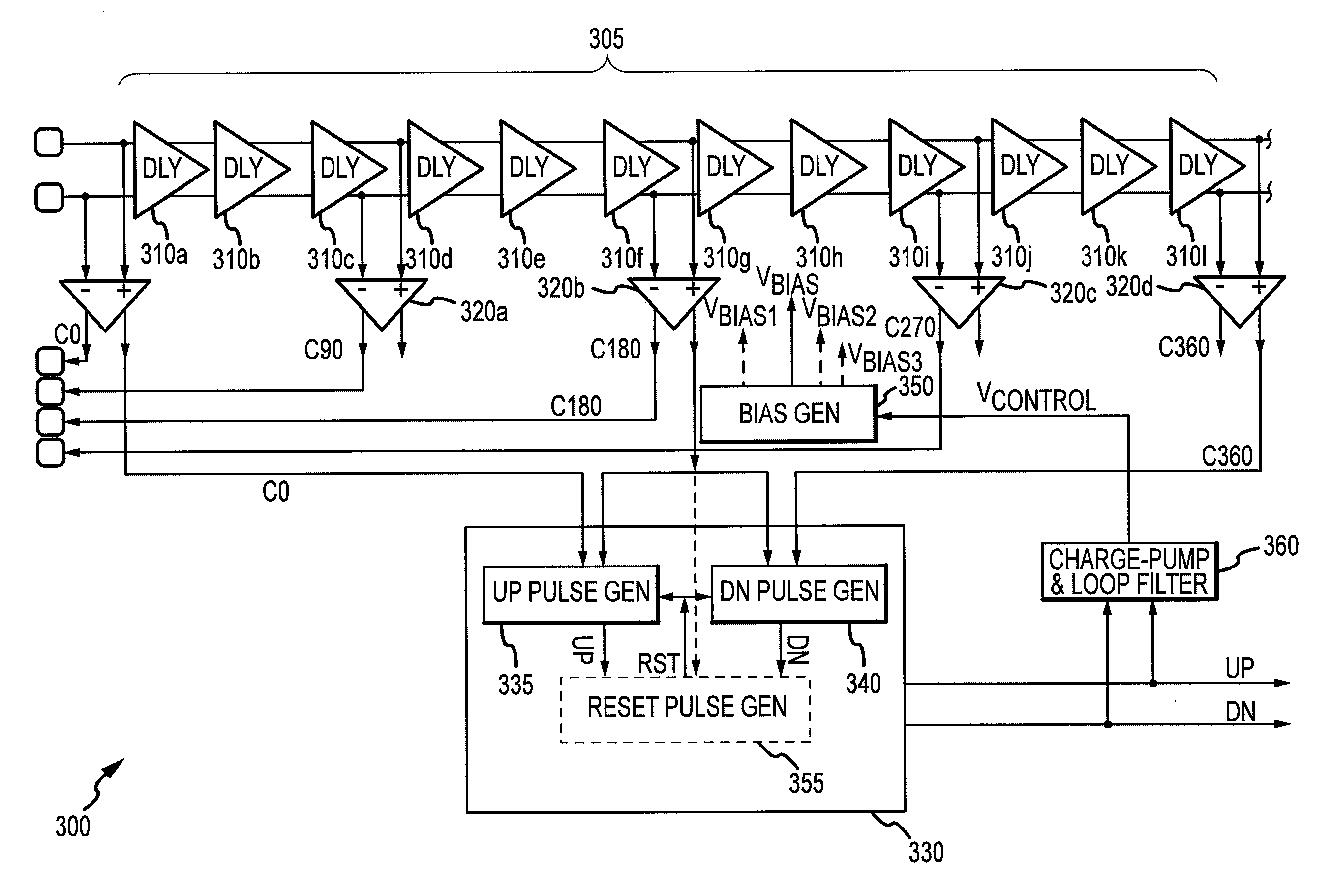
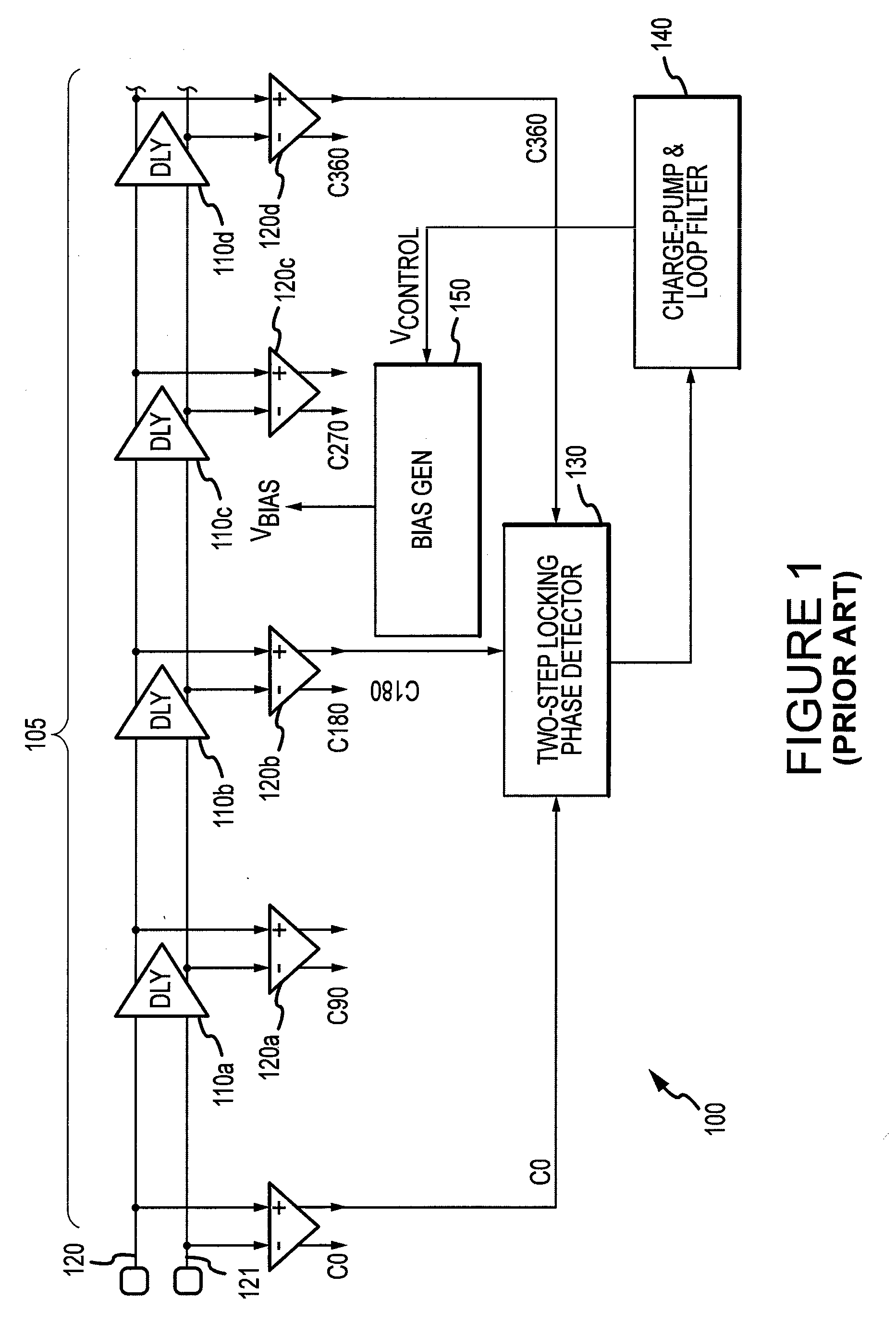
[0021]An embodiment of a multi-phase clock signal generator 300 according to an embodiment of the present invention is shown schematically in FIG. 3. While one delay element per tap may be used in some embodiments of the present invention, as was described above with reference to FIG. 1, the delay line 305 of FIG. 3 includes twelve delay elements 310a-l. Three delay elements are provided for each tap 320a-d. Using multiple delay elements per tap may allow greater flexibility in the range of delay that can be provided...


PUM


Abstract

A multi-phase signal generators and methods for generating multi-phase signals are described. In one embodiment, a clock generator generates quadrature signals including those having 90, 180, 270 and 360 degrees phase difference with a first signal. The rising edge of an intermediate signal is compared with the rising edges of two of the other signals to generate an UP and DN pulse signal, respectively. The UP and DN signals are used to adjust the delay of a delay line producing the signals to synchronize the signals. In some embodiments, a reset signal generator is used to truncate the UP or DN signal pulse.

Description

TECHNICAL FIELD[0001]Embodiments of the invention relate generally to signal generating systems, and more particularly, in one or more embodiments to methods and systems for fast initializing a multi-phase clock signal generator.BACKGROUND OF THE INVENTION[0002]Periodic signals are used in a variety of electronic devices. One type of periodic signals are clock signal s that can be used to establish the timing of a signal or the timing at which an operation is performed on a signal. For example, data signals are typically coupled to and from memory devices, such as synchronous dynamic random access memory (“SDRAM”) devices, in synchronism with a clock or data strobe signal. More specifically, read data signals are typically coupled from a memory device in synchronism with a read data strobe signal. The read data strobe signal typically has the same phase as the read data signals, and it is normally generated by the same memory device that is outputting the read data signals. Write da...

Claims


Application Information

Patent Timeline
IPC IPC(8): H03L7/06G06F1/04
CPCG06F1/06G11C7/1072G11C7/22H03L7/0818G11C11/4076H03L7/0812H03L7/10G11C7/222H03L7/0816H03L7/0814
Inventor MA, YANTAO
Owner MICRON TECH INC
Why Eureka
Try Eureka