Projector with reduced speckle contrast

a projector and contrast technology, applied in the field of projectors, can solve the problems of affecting the viewing experience of users, and viewers' uncomfortable viewing experien

Active Publication Date: 2010-04-08
HON HAI PRECISION IND CO LTD
View PDF1 Cites 21 Cited by
  • Summary
  • Abstract
  • Description
  • Claims
  • Application Information

AI Technical Summary

Problems solved by technology

In laser projectors, speckles of an image occur due to the interference of the light emitting from laser light sources.
The speckles can mask ...

Method used


Image

  • Projector with reduced speckle contrast
  • Projector with reduced speckle contrast
  • Projector with reduced speckle contrast

Examples


Embodiment Construction

[0012]Embodiments of the present disclosure will now be described in detail below, with reference to the accompanying drawings.

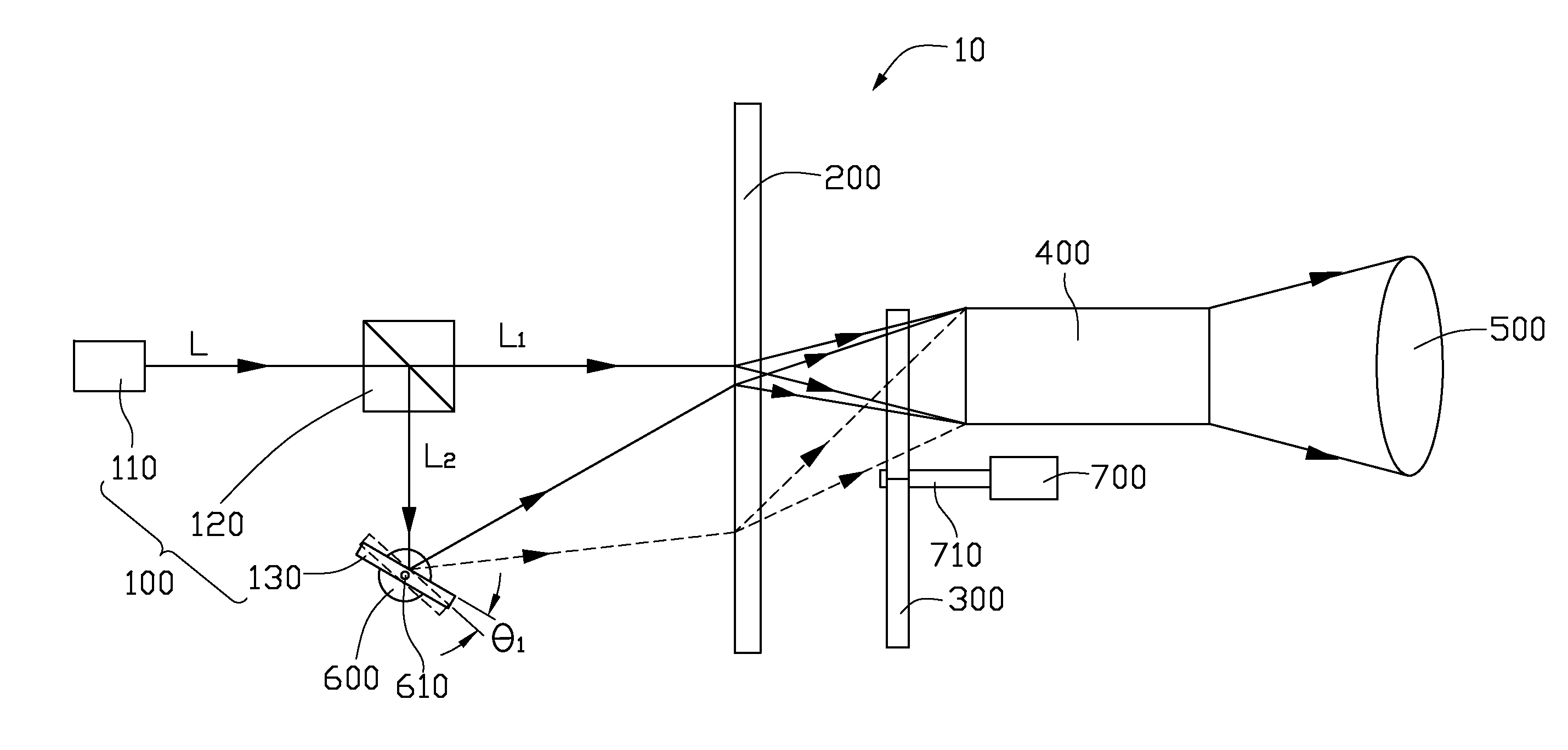
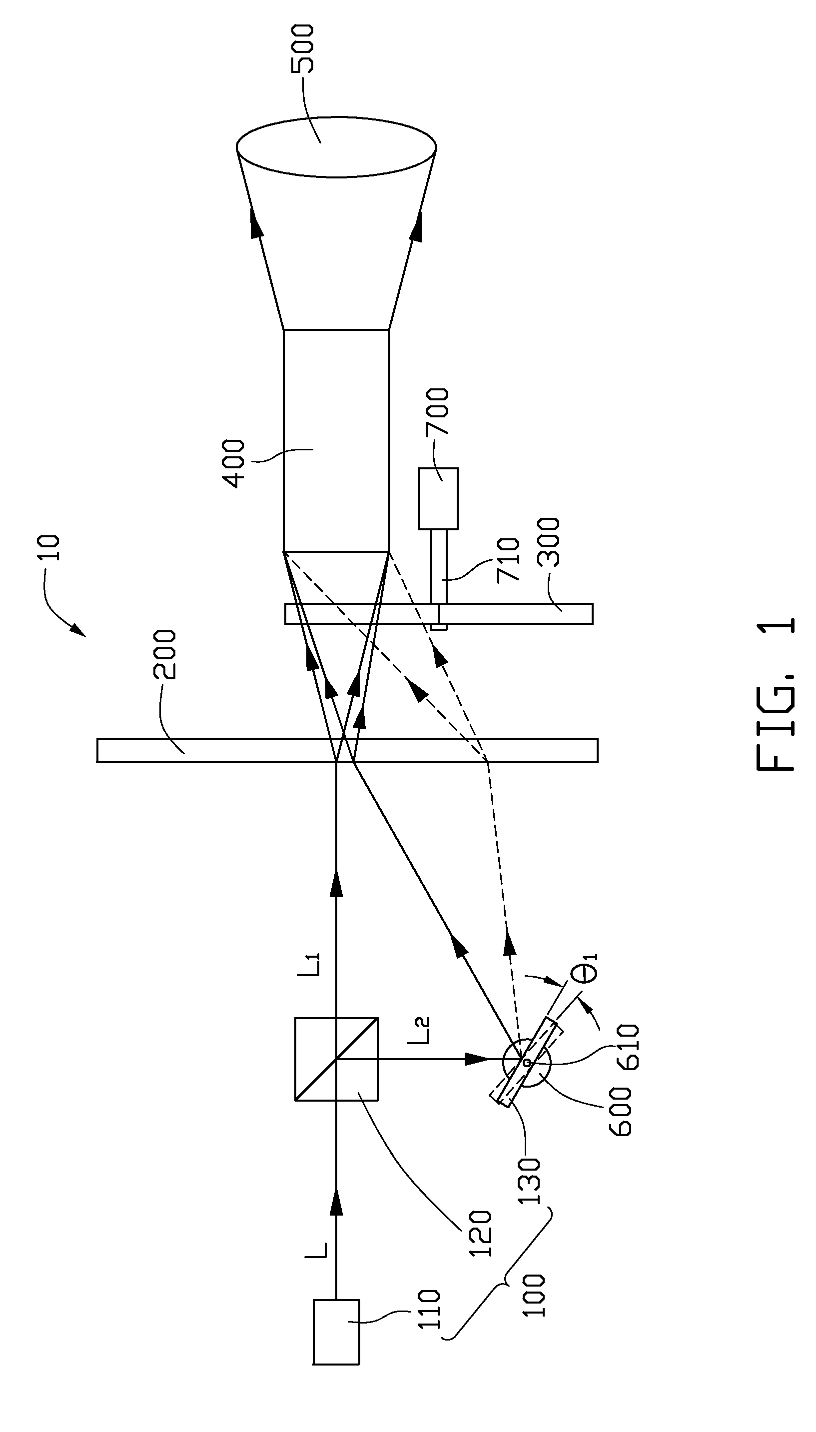
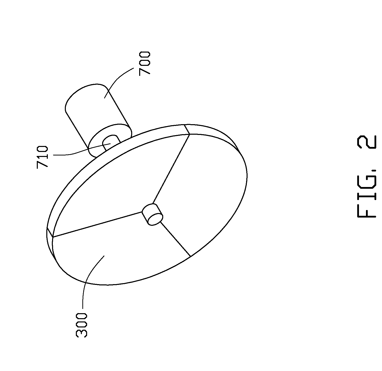
[0013]Referring to FIG. 1, a projector 10, according to a first exemplary embodiment, is shown. The projector 10 includes a light source module 100, a diffuser 200, a fluorescent plate 300, a light tunnel 400, an illumination system 500, a first driver 600, and a second driver 700. The diffuser 200, the fluorescent plate 300, the light tunnel 400, and the illumination system 500 are arranged along the light path of the light beam emitting from the light source module 100 in sequence.

[0014]The light source module 100 includes a light source 110, a dichroic device 120, and a reflector 130. The light source 110 is a laser light source, such as a laser diode. The dichroic device 120 is positioned in the light path of a first light beam L emitting from the light source 110 to diverge the first light beam L into a second light beam L1 and a third light beam L2. Th...


PUM


Abstract

A projector includes a light source module, a diffuser for diffusing the light beam emitting from the light source module, and a fluorescent plate. The light source module includes a light source capable of emitting a first light beam, a dichroic device for diverging the first light beam into a second light beam and a third light beam, and a reflector with a moving frequency exceeding 20 Hz configured for reflecting the third light beam. The fluorescent plate is configured for converting the light beam passing through the diffuser into at least three kinds colored light beams.

Description

BACKGROUND[0001]1. Technical Field[0002]The present disclosure relates to projectors and, particularly, to a projector with reduced speckle contrast.[0003]2. Description of Related Art[0004]In laser projectors, speckles of an image occur due to the interference of the light emitting from laser light sources. The speckles can mask part or all image display area, negatively affecting the users' viewing experience. Speckles may cause uncomfortable viewing experience for viewers.[0005]What is needed, therefore, is a projector which can overcome or alleviate the above-described problem.BRIEF DESCRIPTION OF THE DRAWING[0006]Many aspects of the present projector can be better understood with reference to the accompanying drawings. The components in the drawing are not necessarily drawn to scale, the emphasis instead being placed upon clearly illustrating the principles of the present projector.[0007]FIG. 1 is a schematic view of a projector including a fluorescent plate according to a firs...

Claims


Application Information

Patent Timeline
IPC IPC(8): G02B27/48G02B27/18G03B21/28
CPCG02B27/48G02B2207/113H04N9/3197G03B33/08H04N9/3161G03B21/28
Inventor CHEN, CHIU-PING
Owner HON HAI PRECISION IND CO LTD
Why Eureka
Try Eureka