Light guiding plate

Inactive Publication Date: 2010-04-08
LIN FENG LI
View PDF8 Cites 20 Cited by
  • Summary
  • Abstract
  • Description
  • Claims
  • Application Information

AI Technical Summary

Benefits of technology

[0014]As mentioned above, the light guiding plate of the present invention has a first surface with the first microstructure array, and the materials of the light guiding plate body and the total internal reflection destruction materials are different. Compared with the prior art, the light guiding plate body of the present invention can be manufactured by the rolling process, so that the cost for manufacturing machines and processes can be reduced

Problems solved by technology

However, the size of the light-guiding plate 13 has sufficiently increased, so that the required injection pressure for

Method used


Image

  • Light guiding plate
  • Light guiding plate
  • Light guiding plate

Examples


Example

First Embodiment

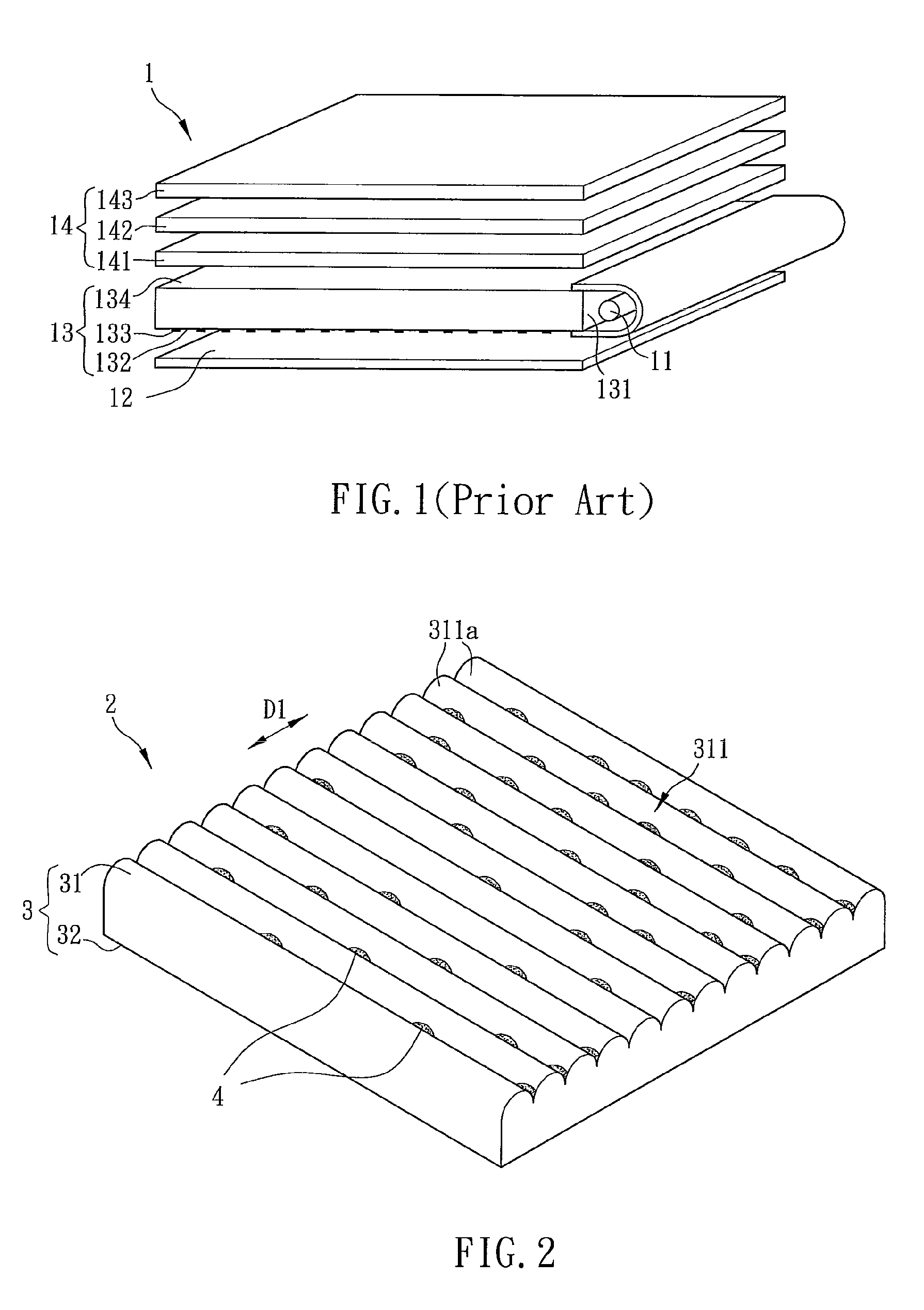
[0027]With reference to FIG. 2, a light guiding plate 2 according to a first embodiment of the present invention includes a light guiding plate body 3 and a plurality of total internal reflection destruction materials 4. In the embodiment, the light guiding plate 2 is used in a side-edged type backlight module for example.

[0028]The light guiding plate body 3 has a first surface 31 and a second surface 32 disposed opposite to each other. The first surface 31 has a first microstructure array 311, which may include prisms, convex lenses, lenticular lenses, concave lenses, Fresnel lenses, or their combinations. In this embodiment, the first microstructure array 311 includes a plurality of lenticular lenses 311a, which are arranged in an array. As shown in FIG. 2, the lenticular lenses 311a are arranged in parallel along a first direction D1, which means that the lenticular lenses 311a are arranged in one dimension.

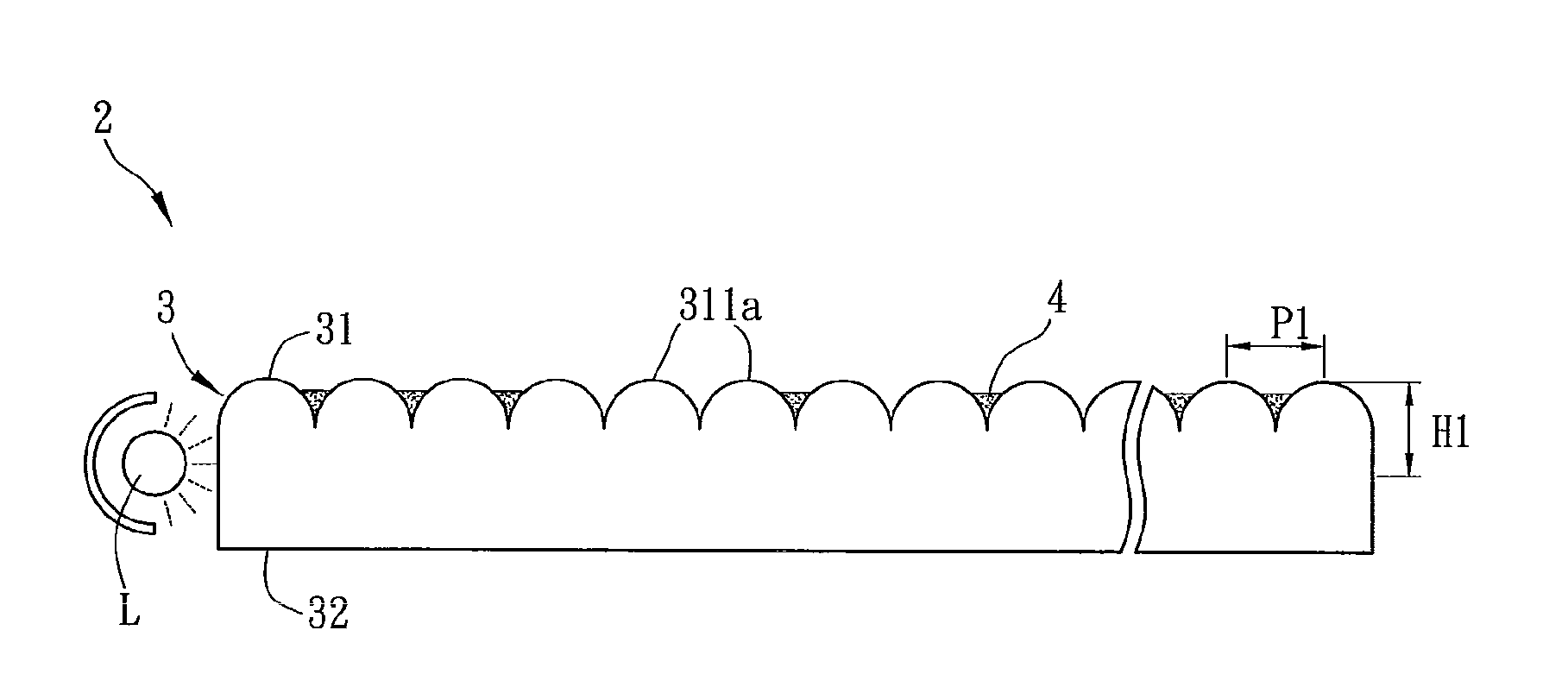
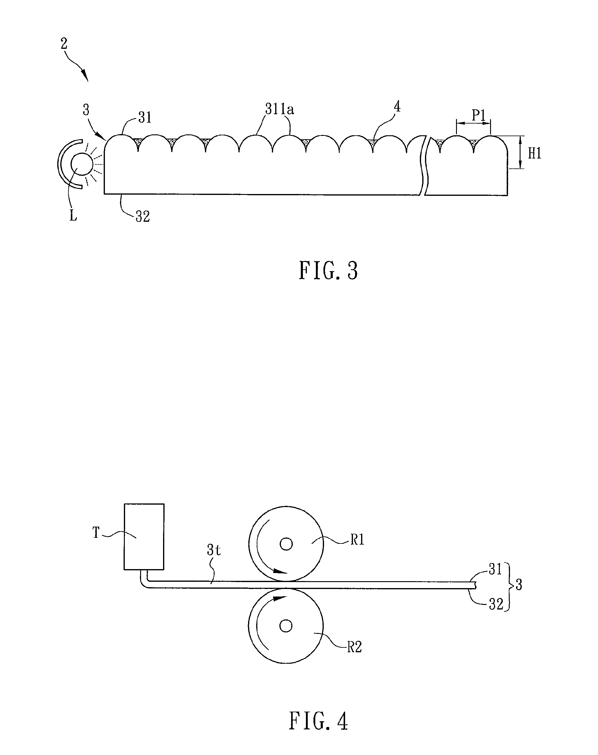
[0029]FIG. 3 is a sectional view of the light guiding pl...

Example

Second Embodiment

[0036]FIG. 5 is a schematic diagram of a light guiding plate 5 according to a second embodiment of the present invention, and FIG. 6 is a sectional view of the light guiding plate 5 along the line A-A of FIG. 5. As shown in FIGS. 5 and 6, the light guiding plate 5 includes a light guiding plate body 6 and a plurality of total internal reflection destruction materials 7.

[0037]The light guiding plate body 6 has a first surface 61 and a second surface 62 disposed opposite to each other. The first surface 61 has a first microstructure array 611, which includes a plurality of lenticular lenses 611a in this embodiment. As shown in FIG. 5, the lenticular lenses 611a are arranged in parallel along a first direction D1. The technical features of the first microstructure array 611 are the same as those of the first microstructure array 311 of the first embodiment, so the detailed descriptions thereof will be omitted.

[0038]The second surface 62 of the light guiding body 6 has...

Example

Third Embodiment

[0044]With reference to FIG. 8, the difference between the light guiding plate 5a of the third embodiment and the light guiding plate 5 of the second embodiment is in that the first direction D1 is in parallel to the second direction D2, and the total internal reflection destruction materials 7a are disposed on both of the first and second surfaces 61a and 62. In this embodiment, the lenticular lenses 611a of the first surface 61 are arranged in parallel along the first direction D1, and the prisms 621a of the second surface 62 are arranged in parallel along a first direction D2.

[0045]Hereinafter, the fabrication of the light guiding plate body 6a according to the third embodiment will be described with reference to FIG. 9.

[0046]First, the melted transparent polymer material is outputted from a tank T1 and then pressed by an embossed roller R1 with predetermined concave pattern and a planar roller R2 for forming the first microstructure array on the first surface 61...


PUM


Abstract

A light guiding plate includes a light guiding plate body and a plurality of total internal reflection destruction materials. The light guiding plate body has a first surface and a second surface opposite to the first surface. The first surface has a first microstructure array. The material of the total internal reflection destruction materials is different from the material of the light guiding body. The total internal reflection destruction materials are unevenly distributed on the first surface and/or the second surface.

Description

CROSS REFERENCE TO RELATED APPLICATIONS[0001]This Non-provisional application claims priority under 35 U.S.C. §119(a) on Patent Application No(s). 097138248 filed in Taiwan, Republic of China on October 3, 2008, the entire contents of which are hereby incorporated by reference.BACKGROUND OF THE INVENTION[0002]1. Field of Invention[0003]The present invention relates to an optical sheet and, in particular, to a light guiding plate.[0004]2. Related Art[0005]According to the development of display technology, the traditional CRT display apparatuses are replaced by the LCD apparatuses recently. In practice, the LCD apparatuses have been applied to various kinds of electronic products such as notebook computers, televisions and desktop monitors.[0006]In general, an LCD apparatus includes a backlight module and an LCD panel. Since the LCD panel can not emit light spontaneously, the backlight module is necessary to provide sufficient brightness and even light source for enabling the LCD pan...

Claims


Application Information

Patent Timeline
IPC IPC(8): F21V7/22
CPCG02B6/0038G02B6/0065G02B6/0043
Inventor LIN, FENG-LI
Owner LIN FENG LI
Why Eureka
Try Eureka