Radial flow steam injection heater

a radial flow, heater technology, applied in the direction of mixing, lighting and heating equipment, transportation and packaging, etc., can solve the problems of condensing characteristics, inconsistent heat transfer across the heater profile, and clogging of the heater with solid composition of slurry, etc., to increase the effectiveness of the radial flow steam injection heater

Active Publication Date: 2010-04-08
HYDRO THERMAL
View PDF11 Cites 17 Cited by
  • Summary
  • Abstract
  • Description
  • Claims
  • Application Information

AI Technical Summary

Benefits of technology

[0008]In one embodiment, a regulating member surrounds the mixing tube. The regulating member is selectively movable relative to the mixing tube to selectively expose a number of the steam injection openings to the pressurized supply of steam within the steam chamber. In one embodiment, the movement of the regulating member along the mixing tube is controlled by an actuator member, which may be either manually controlled or automatically controlled. As the actuator member moves the regulating member along the outer surface of the mixing tube, an increasing number of the steam injection openings are exposed, thus allowing a larger amount of steam to flow into the mixing tube. In an alternate embodimen

Problems solved by technology

While this type of steam injection heater works well with various types of liquids and slurries having a relatively low solid composition, the heater has several drawbacks when heating slurries having a relatively high solid composition.
When used with these types of slurries, the solid composition of a slurry often clogs the heater at the point in the heater in which the slurry changes directions.
In addition to the drawback set forth above, presently available direct contact steam injection

Method used


Image

  • Radial flow steam injection heater
  • Radial flow steam injection heater
  • Radial flow steam injection heater

Examples


Embodiment Construction

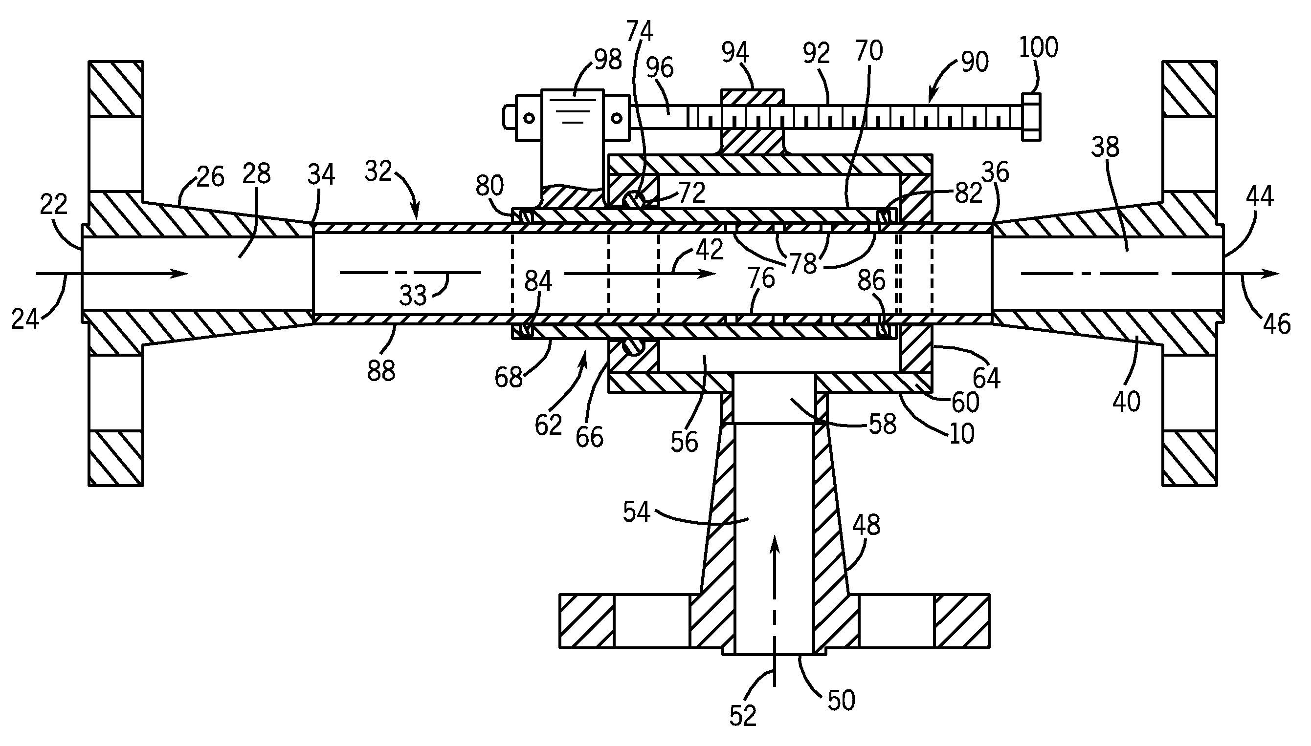
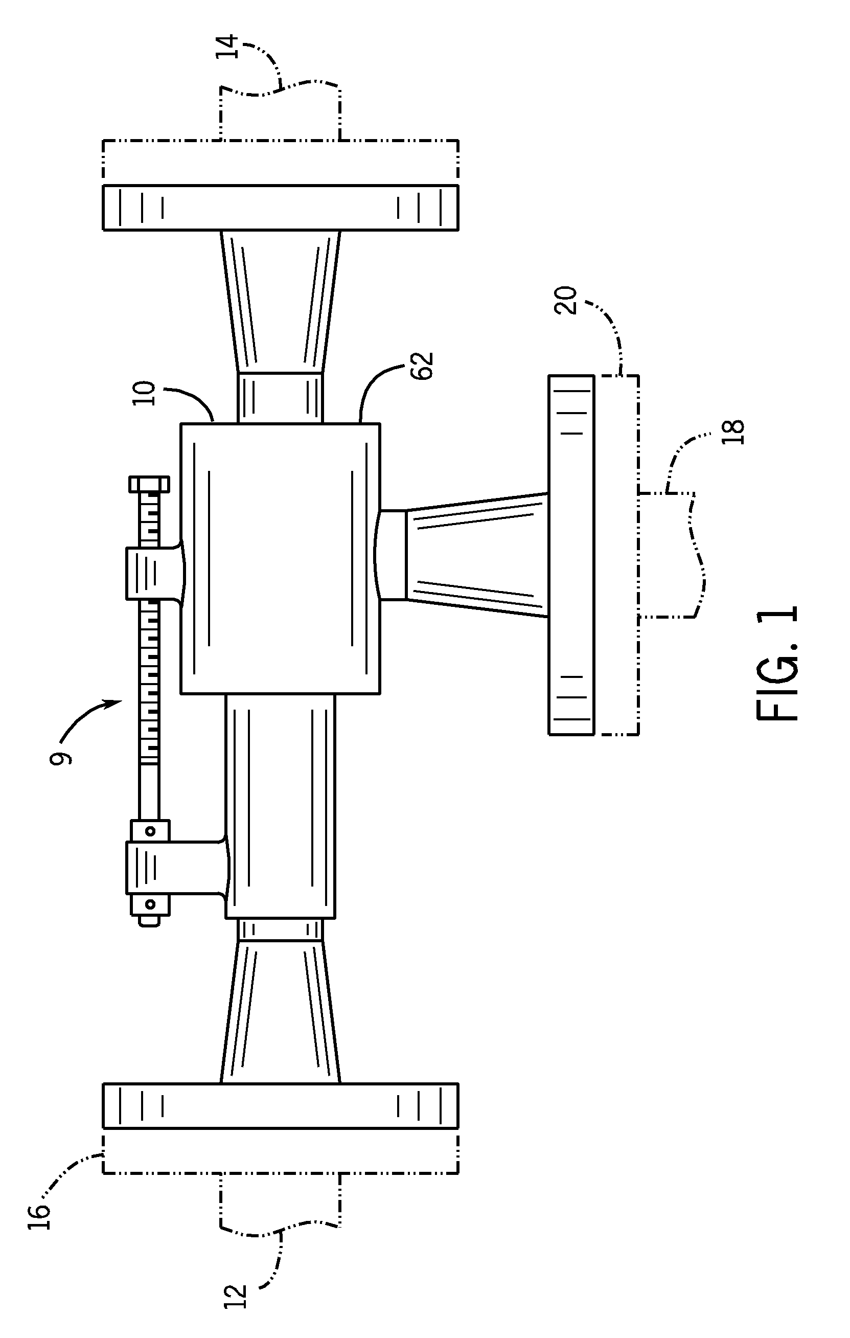
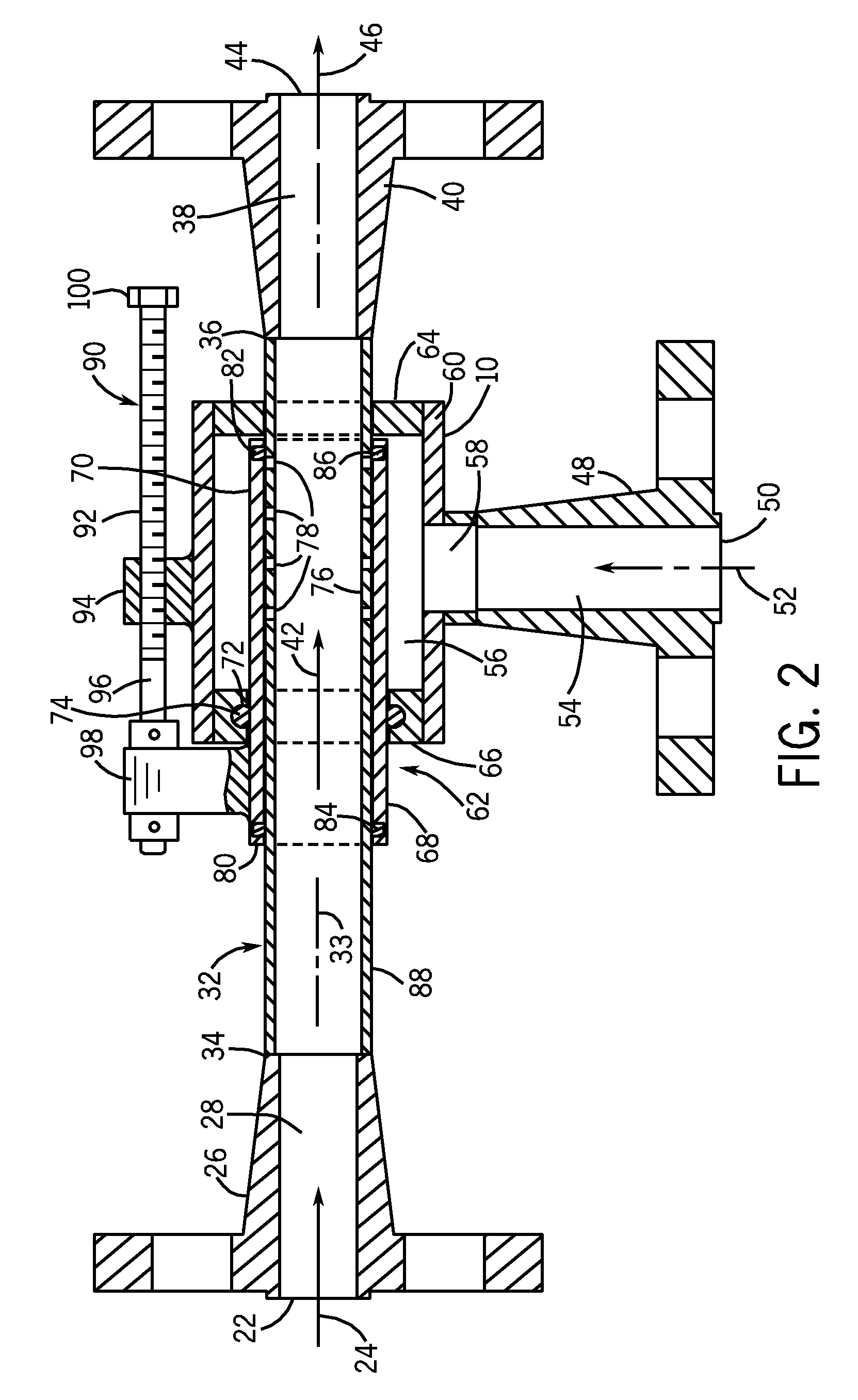
[0021]FIG. 1 illustrates a radial flow mixing device 9 in accordance with the present disclosure. The mixing device 9 is configured to allow a first liquid or gas to be mixed with a second liquid or gas as the first liquid or gas passes through the mixing device 9. Throughout the following description, the mixing device 9 will be shown and described as a steam injection heater 10 that receives a flow of material to be heated and injects steam to heat the material flowing through the steam injection heater 10. However, it should be understood that the mixing device 9 could be utilized to mix various other liquids and / or gases while operating within the scope of the present disclosure.

[0022]As illustrated in FIG. 1, the steam injection heater 10 is positioned within a flow of material to be heated. The material, such as a liquid or slurry, flows from an inlet pipe 12 to an outlet pipe 14, each of which include an attachment flange 16. The steam injection heater 10 receives a flow of s...


PUM


Abstract

A radial flow steam injection heater that injects a selected amount of steam into a product flow to heat the product flow. The steam injection heater includes a mixing tube that receives the product flow to be heated. The mixing tube includes a series of steam injection holes that are positioned within a steam chamber defined by the heater body. Pressurized steam within the steam chamber flows into the mixing tube in a direction transverse to the flow axis through the steam injection holes. A regulating member is selectively movable relative to the mixing tube to expose the steam injection holes to the steam chamber to control the amount of steam utilized to heat the product flow.

Description

CROSS-REFERENCE TO RELATED APPLICATION[0001]The present application is based on and claims priority to U.S. Provisional Patent Application Ser. No. 61 / 102,378 filed on Oct. 3, 2008.BACKGROUND OF THE INVENTION[0002]The present disclosure generally relates to a mixing device for combining and mixing liquids or gases. More specifically, the present disclosure relates to a steam injection heater in which a supply of heated steam flows inward into a slurry or liquid to be heated, where the flow path for the liquid to be heated does not include any flow obstructions.[0003]In direct contact steam injection heaters, steam is directly mixed with a liquid or slurry product to heat the liquid or slurry product. Direct contact steam injection heaters are effective at transferring heat from steam to the liquid or slurry material. Steam injection heaters provide rapid heat transfer with virtually no heat loss to the atmosphere, and also transfer both the latent and available sensible heat of the ...

Claims


Application Information

Patent Timeline
IPC IPC(8): B01F15/06B01F15/02
CPCB01F5/0475B01F5/0485F28C3/06B01F15/0201B01F15/0261B01F15/00025B01F25/31425B01F25/3142B01F35/1452B01F35/71B01F35/718051
Inventor ZAISER, GARYZAISER, JAMESSCHREIB, KURT R.VAN DIXHORN, LEE RICHARDMUENSTER, THOMAS
Owner HYDRO THERMAL
Why Eureka
Try Eureka