Optical fiber cable inlet device and telecommunications enclosure system

a technology of optical fiber cable and inlet device, which is applied in the direction of optics, fibre mechanical structures, instruments, etc., can solve the problems of service interruption and difficult cleaning of optical interfa

Active Publication Date: 2010-04-08
CORNING RES & DEV CORP
View PDF47 Cites 98 Cited by
  • Summary
  • Abstract
  • Description
  • Claims
  • Application Information

AI Technical Summary

Problems solved by technology

This system provides for the optical connection to be made proximate to the wall of a terminal closure which may cause service interruptions when subjected to harsh environmental conditions.
Finally, the design of the connector and receptacle make cleaning of the optical interface difficult, prior to the installation of service.

Method used


Image

  • Optical fiber cable inlet device and telecommunications enclosure system
  • Optical fiber cable inlet device and telecommunications enclosure system
  • Optical fiber cable inlet device and telecommunications enclosure system

Examples


Embodiment Construction

[0051]In the following detailed description of the preferred embodiments, reference is made to the accompanying drawings, which form a part hereof, and in which is shown by way of illustration specific embodiments in which the invention may be practiced. The illustrated embodiments are not intended to be exhaustive of all embodiments according to the invention. It is to be understood that other embodiments may be utilized and structural or logical changes may be made without departing from the scope of the present invention. The following detailed description, therefore, is not to be taken in a limiting sense, and the scope of the present invention is defined by the appended claims.

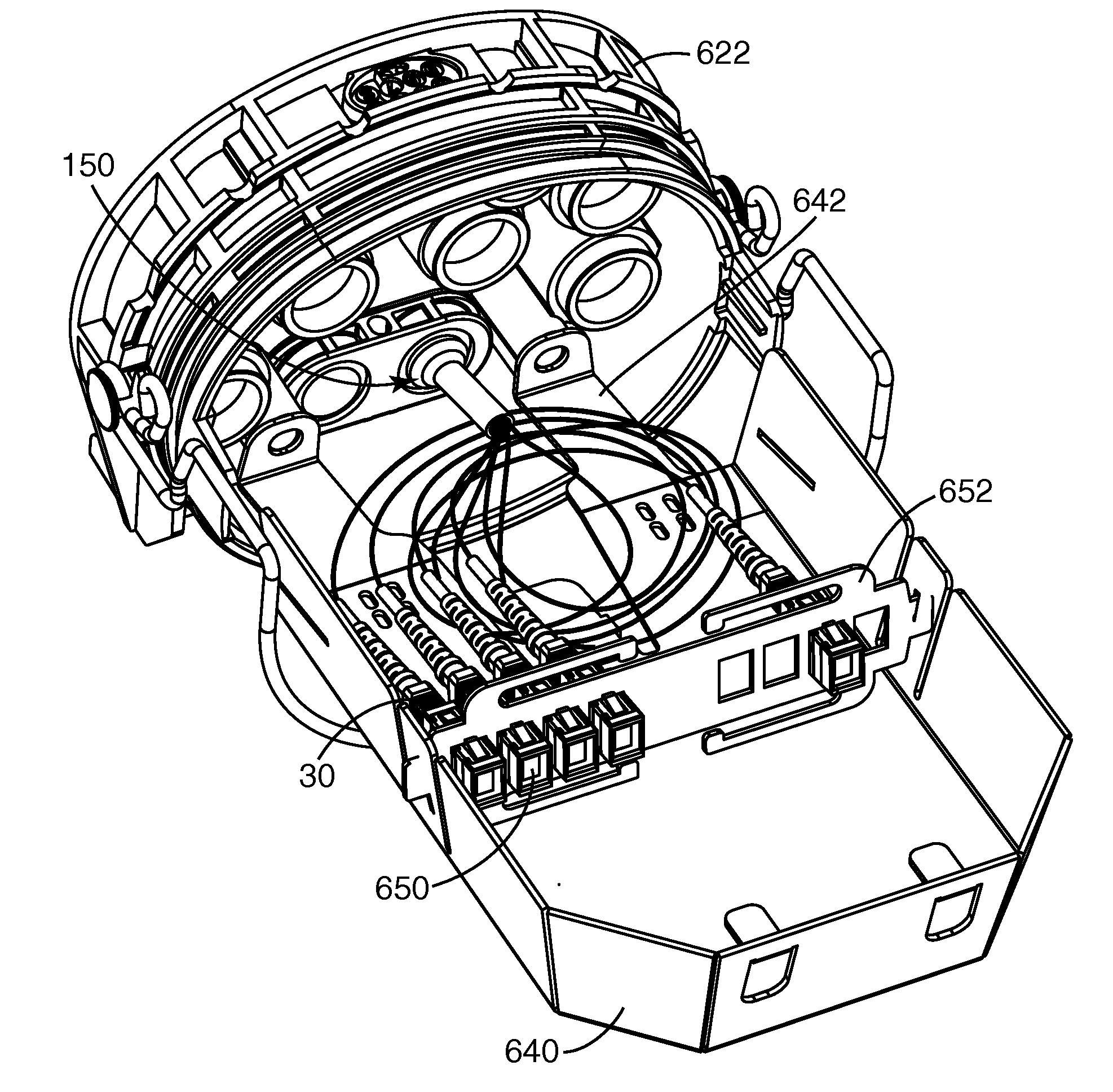
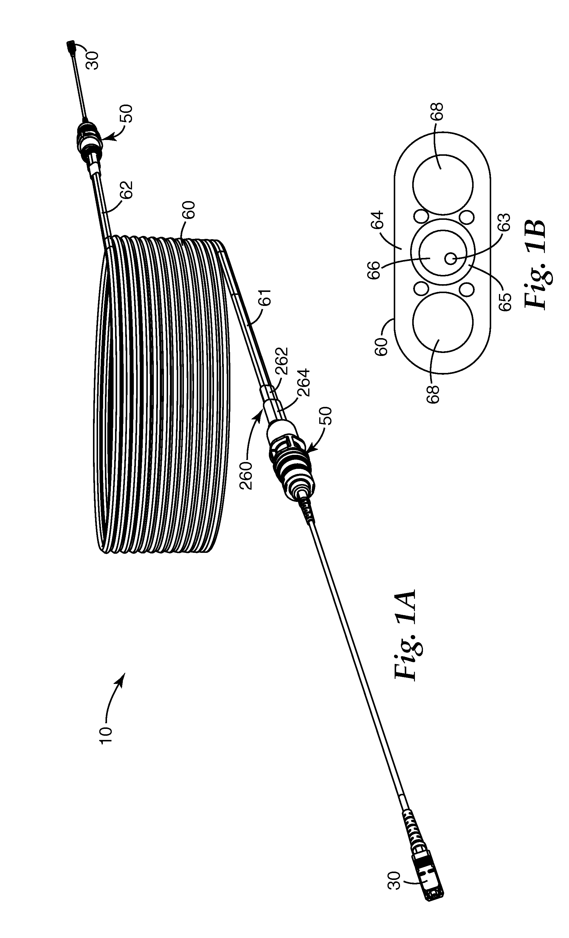
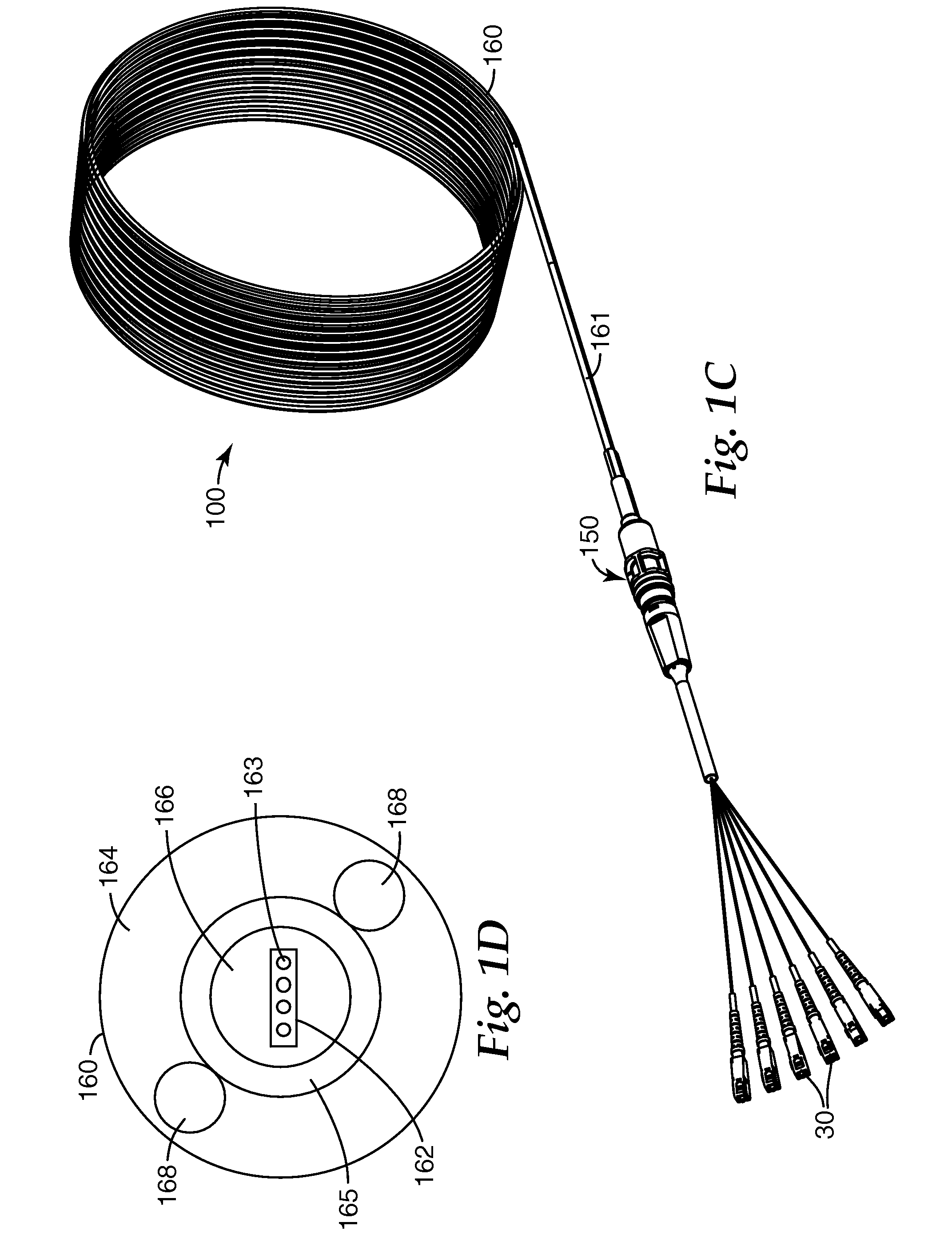
[0052]Exemplary embodiments herein provide an inlet device for the insertion of an optical fiber cable into a telecommunications enclosure. Particular advantages of the design of the present inlet device include a robust housing and the ability to accommodate either single fiber cables or multi-fiber cabl...


PUM


Abstract

An inlet device is described for inserting a cable containing optical fibers into a telecommunications enclosure. The inlet device includes a housing with a strength member securing section configured to fasten at least one strength member to the housing. The inlet device further includes a fiber guide device. The inlet device may be used in a single fiber optical cable assembly or multi-fiber optical cable assembly. A method for preparing a cable assembly is also described. A telecommunications enclosure including an inlet device is also described.

Description

FIELD OF THE INVENTION[0001]The present invention relates to an inlet device for inserting a cable containing optical fibers into a telecommunication's enclosure, e.g. into a terminal closure, pre-stubbed terminal, optical network terminal or other junction box.BACKGROUND OF THE INVENTION[0002]Telecommunication cables are ubiquitous and used for distributing all manner of data across vast networks. The majority of cables are electrically conductive cables (typically copper), although the use of optical fiber cables is growing rapidly in telecommunication systems as larger and larger amounts of data are transmitted. Additionally, as data transmissions increase, the fiber optic network is being extended closer to the end user which can be a premise, business, or a private residence.[0003]As telecommunication cables are routed across data networks, it is necessary to periodically open the cable so that one or more telecommunication lines therein may be spliced, thereby allowing data to...

Claims


Application Information

Patent Timeline
Patent Type & Authority Applications(United States)
IPC IPC(8): G02B6/46G02B6/00G02B6/36G02B6/44
CPCG02B6/3636G02B6/4444G02B6/4477G02B6/4442G02B6/44775G02B6/44528
Inventor PARIKH, RUTESH D.ALLEN, WILLIAM G.REBERS, KENNETH D.VAN ALLEN, JOSEPH M.PARRETT, GEORGE W.BLUDAU, THOMAS E.
Owner CORNING RES & DEV CORP
Why Eureka
Try Eureka