Chain tensioner

a chain tensioner and tensioner technology, applied in the direction of belts/chains/gearrings, mechanical instruments, belts/chains/gearrings, etc., can solve the problems of inability to loosen threaded parts, easy head breakage,

Inactive Publication Date: 2010-04-08
NTN CORP
View PDF3 Cites 11 Cited by
  • Summary
  • Abstract
  • Description
  • Claims
  • Application Information

AI Technical Summary

Benefits of technology

[0020]According to the present invention, since the externally threaded member is fixed in position with an adhesive, the externally threaded member nev

Problems solved by technology

The externally threaded member is preferably made of aluminum so that if attempts are made to forcibly loosen th

Method used


Image

  • Chain tensioner
  • Chain tensioner
  • Chain tensioner

Examples


Embodiment Construction

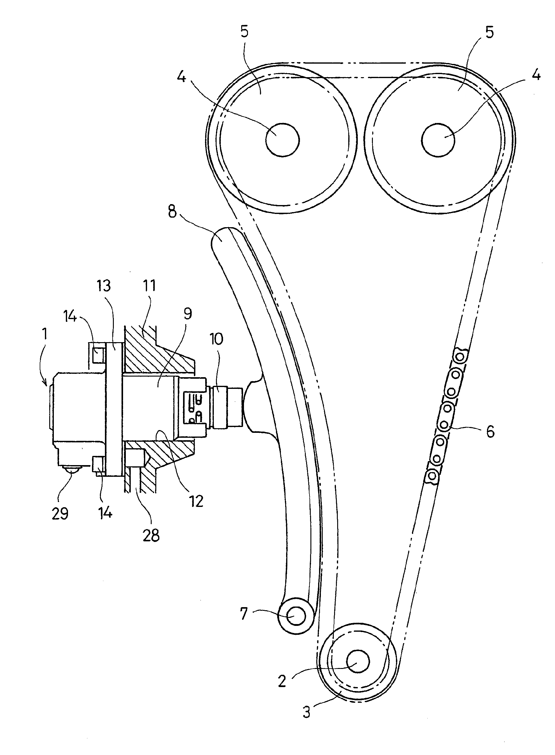
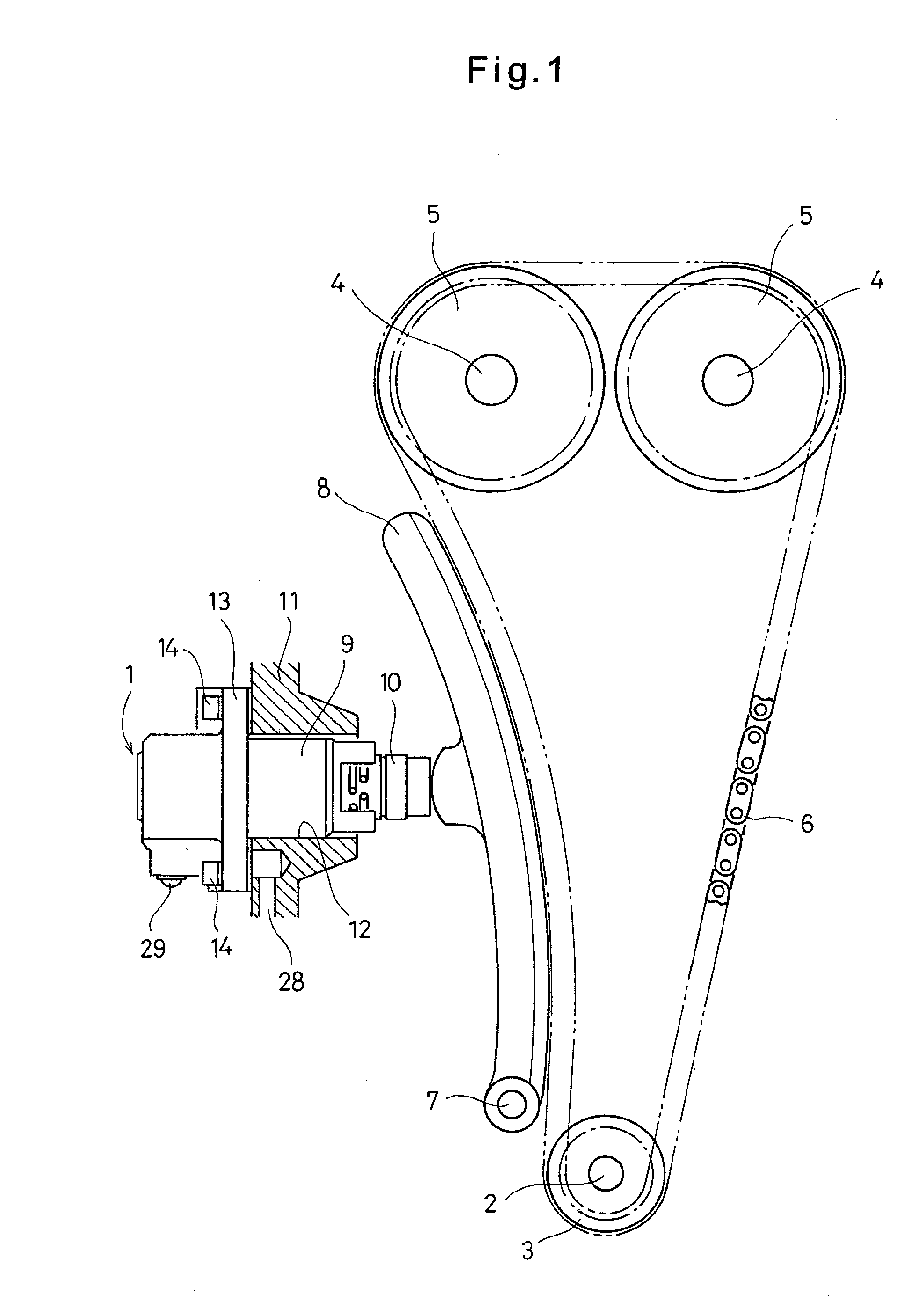
[0029]FIG. 1 shows a chain transmission device including a chain tensioner 1 according to the first embodiment of the present invention. The chain transmission device includes a sprocket 3 fixed to an engine crankshaft 2, sprockets 5 fixed to respective camshafts 4, and a chain 6 through which the sprockets 3 and 5 are coupled together. Thus, the rotation of the crankshaft 2 is transmitted to the camshafts 4, thereby rotating the camshafts 4 and opening and closing valves (not shown) of the combustion chambers.

[0030]A chain guide 8 which is pivotable about a pivot shaft 7 is kept in contact with the chain 6. The chain tensioner 1 presses the chain 6 through the chain guide 8.

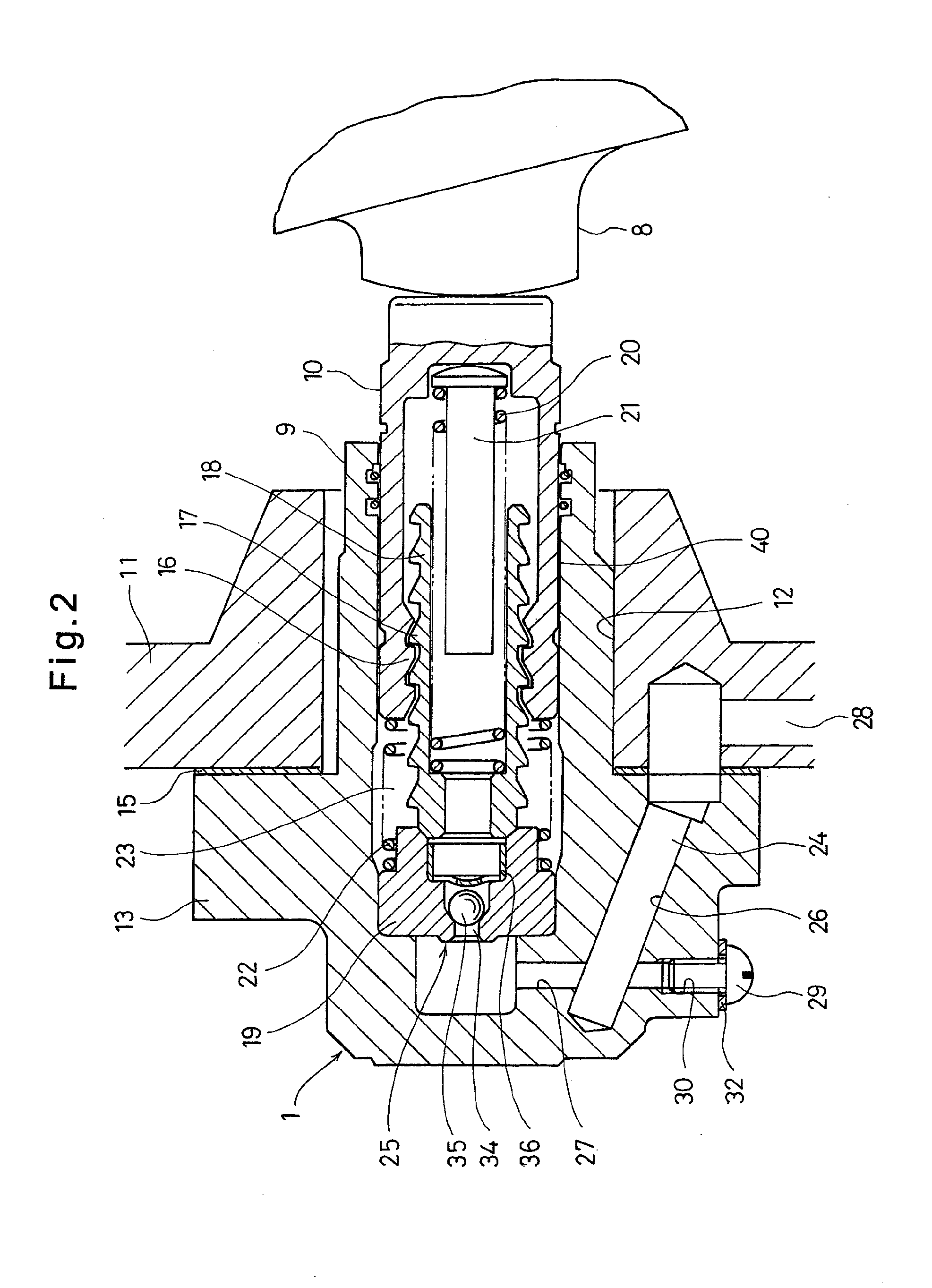
[0031]As shown in FIG. 2, the chain tensioner 1 includes a cylindrical cylinder 9 having an open end and a closed end, and a plunger 10 axially slidably inserted in the cylinder 9. The cylinder 9 is inserted in a tensioner mounting hole 12 formed in an engine cover 11 with its open end disposed in the interior o...


PUM


Abstract

A chain tensioner includes a cylinder inserted in a tensioner mounting hole of an engine cover and having a flange fixed to the outer surface of the engine cover. A plunger is axially slidably mounted in the cylinder. The cylinder is formed with an oil supply passage through which hydraulic oil is introduced into a pressure chamber defined by the cylinder and the plunger. The oil supply passage includes a first hole portion extending inwardly from a mating surface of the flange facing the engine cover, and a second hole portion extending from the outer periphery of the flange to the pressure chamber and intersecting the first hole portion. An externally threaded portion of an externally threaded member is in threaded engagement with an internal thread formed on the second hole portion, thereby closing its outer open end. The externally threaded member is fixed in position with an adhesive applied to its externally threaded portion.

Description

BACKGROUND OF THE INVENTION[0001]This invention relates to a chain tensioner for keeping the tension of a timing belt for driving camshafts of an automotive engine.[0002]In a typical automotive engine, the rotation of the crankshaft is transmitted to camshafts through a timing chain to rotate the camshafts, thereby opening and closing valves of combustion chambers. In order to keep the tension of the chain in an optimum range, a tension adjusting device is frequently used which comprises a chain guide pivotable about a pivot shaft, and a chain tensioner for pressing the chain through the chain guide.[0003]One known chain tensioner used in such a tension adjusting device is disclosed in JP Patent Publication 2007-321899A which includes a cylindrical cylinder having open and closed ends and inserted in a tensioner mounting hole formed in an engine cover with its open end located inside the engine cover. The cylinder has a flange fixed to the outer surface of the engine cover. A plunge...

Claims


Application Information

Patent Timeline
IPC IPC(8): F16H7/08
CPCF16H7/0836F16H7/0848F16H2007/0859F16H2007/0812F16H2007/0857F16H2007/0806
Inventor SATO, SEIJIKITANO, SATOSHIHAYAKAWA, HISASHI
Owner NTN CORP
Why Eureka
Try Eureka