Improved Hybrid Drive

a hybrid drive and storage device technology, applied in the direction of memory address/allocation/relocation, instruments, sustainable buildings, etc., can solve the problems of hybrid drives not living up to their promise, hybrid drives not living up to their expectation, and the cost of non-volatile memory used

Inactive Publication Date: 2010-04-08
GREENLIANT
View PDF6 Cites 109 Cited by
  • Summary
  • Abstract
  • Description
  • Claims
  • Application Information

AI Technical Summary

Benefits of technology

[0007]Accordingly, in the present invention, a non-volatile storage system comprises a hard disk drive (HDD) having a first capacity for storing information therein in a plurality of blocks. The storage system also comprises a non-volatile solid state memory (SSD) having a second capacity, less than the first capacity, for storing information therein. Finally, the storage system comprises a controller having a volatile memory and for controlling the read operation of the HDD and the read / write operation of the SSD. The controller stores in the volatile memory the address of read blocks from the HDD in a first period of time and determines a plurality of the most frequently read blocks in the first period of time. The controller then causes the SSD to store information from the most frequently read blocks from the HDD, and thereafter causes information to be read from the SSD when the storage system is requested to access information from the most frequently read blocks. The controller resets the identity of the most frequently read blocks in the volatile memory after a second period of time, where the second period of time is longer than said first period of time.

Problems solved by technology

However, hybrid drives have not lived up to their promise for a number of reasons.
Nevertheless, hybrid drives have not lived up to their expectation because frequently used programs and data have not been found in the SSD often enough.
In part this is caused by the expense of the non-volatile memory used in the SSD.

Method used


Image

  • Improved Hybrid Drive
  • Improved Hybrid Drive

Examples


Embodiment Construction

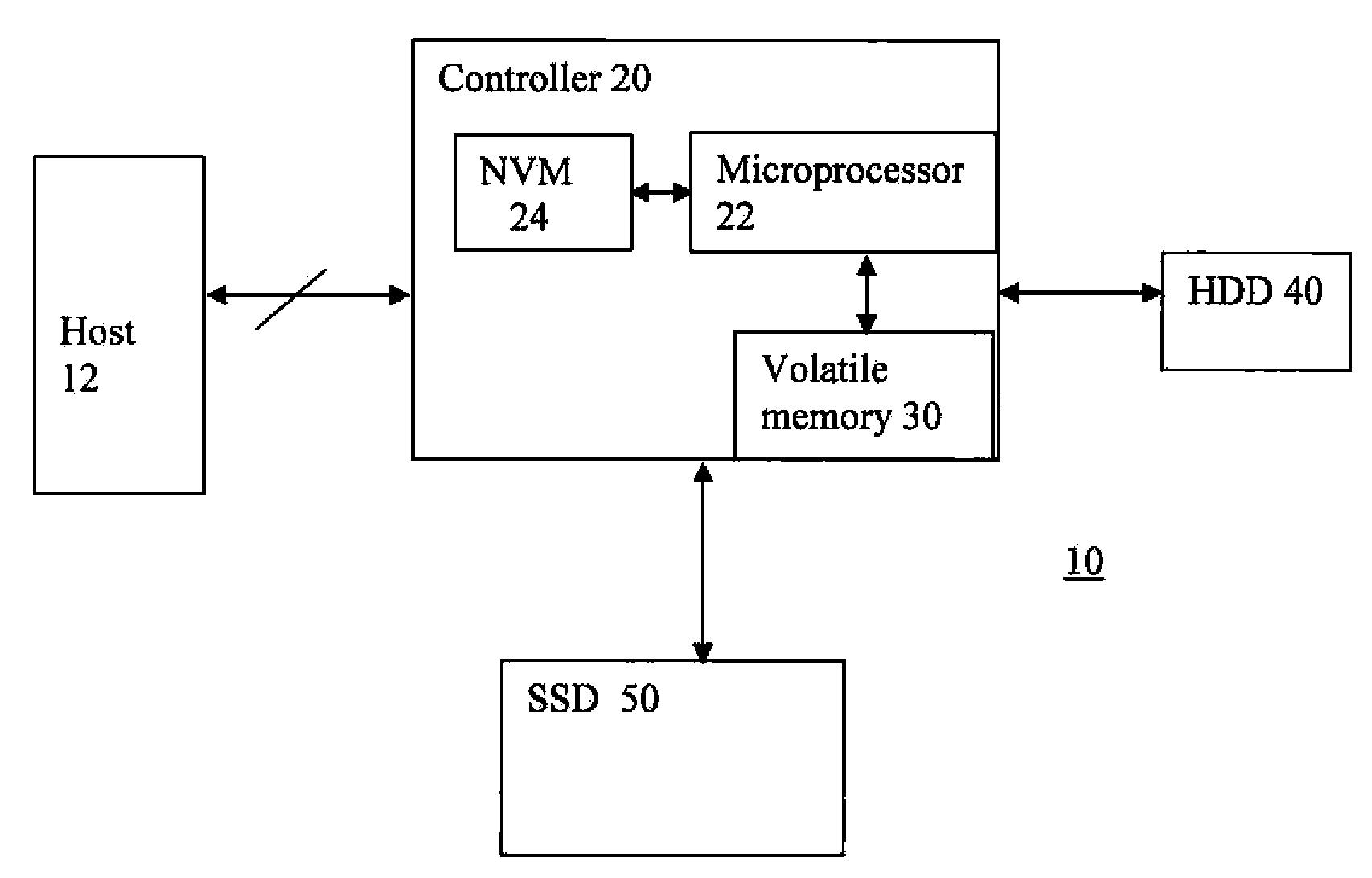
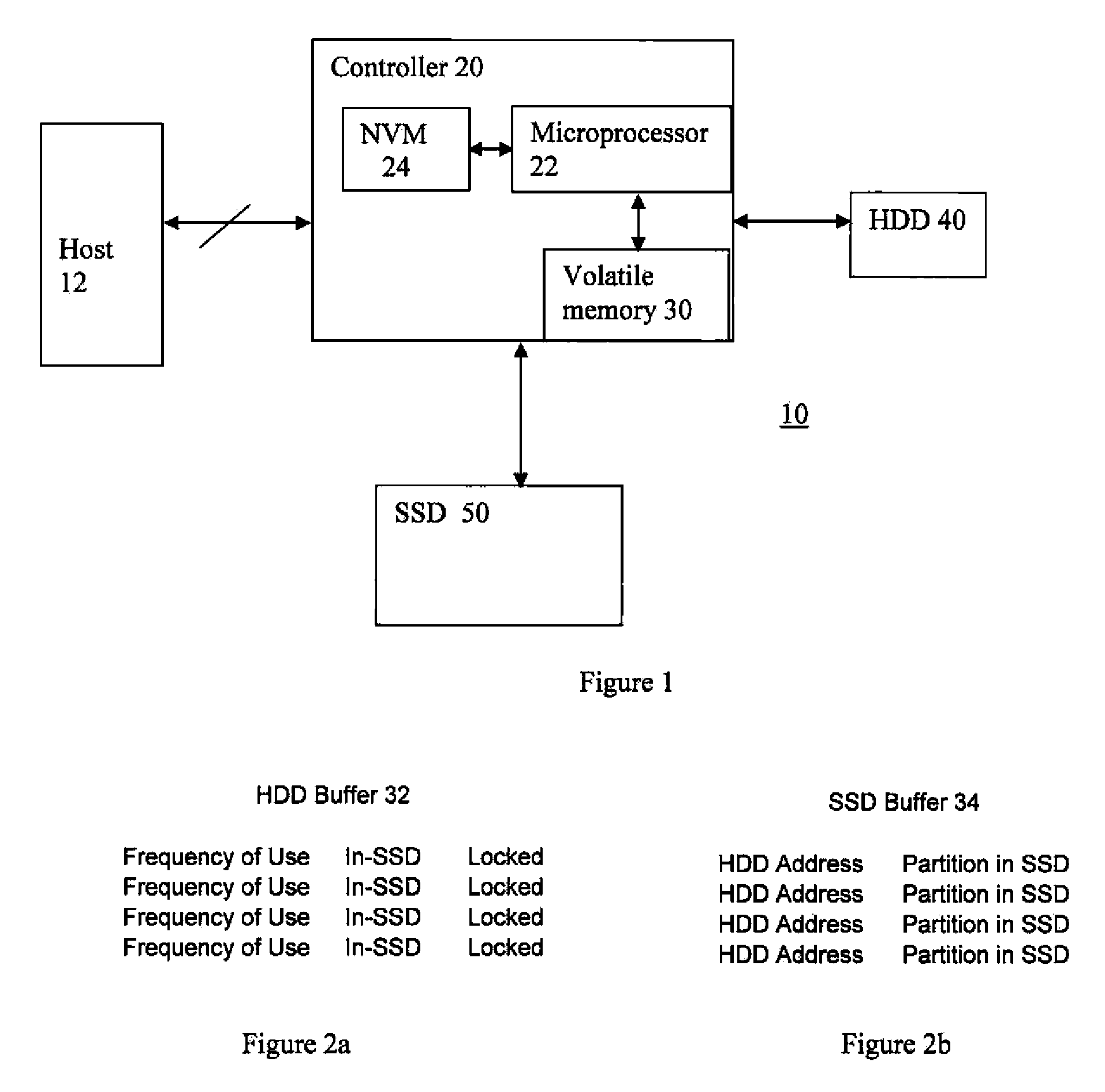
[0011]Referring to FIG. 1 there is shown a block level diagram of an improved non-volatile storage system 10 of the present invention. The system comprises a controller 20 connected to the host device 12. The host device 12 typically is a processor or a computer. The controller 20 comprises a volatile memory 30, a microprocessor 22, and a non-volatile memory (NVM) 24. The NVM 24 stores a program for execution by the microprocessor 22. Of course, the stored program stored in the NVM 24 can also be updated by the host device 12. The microprocessor 22 receives the stored program from the NVM 24 and executes the instructions there on and controls the volatile memory 30. In addition, the controller is connected to a hard disc drive (HDD) 40. Finally, the system 10 comprises a solid state drive (SSD) 50, which is also connected to the controller 20 and is under the control of the controller 20. The microprocessor 22 in executing the stored program from the NVM 24 also controls the operati...


PUM


Abstract

A non-volatile storage system comprises a hard disk drive (HDD) having a first capacity for storing information therein in a plurality of blocks. The storage system also comprises a non-volatile solid state memory (SSD) having a second capacity, less than the first capacity, for storing information therein. Finally, the storage system comprises a controller having a volatile memory and for controlling the read operation of the HDD and the read/write operation of the SSD. The controller stores in the volatile memory the address of read blocks from the HDD in a first period of time and determines a plurality of the most frequently read blocks in the first period of time, The controller then causes the SSD to store information from the most frequently read blocks from the HDD, and thereafter causes information to be read from the SSD when the storage system is requested to access information from the most frequently read blocks. The controller resets the identity of the most frequently read blocks in the volatile memory after a second period of time, where the second period of time is longer than said first period of time.

Description

TECHNICAL FIELD[0001]The present invention relates to an improved storage device that comprises a hard disc drive and a non-volatile memory cache.BACKGROUND OF THE INVENTION[0002]Hybrid drives are well known in the art. A hybrid drive comprises a hard disk drive (HDD) with a solid state drive (SSD) used as a cache memory. The lure of a hybrid drive is that data or program that are frequently accessed from the HDD are stored in the non-volatile memory of the SSD with the SSD acting as a cache for the HDD. As a result, in theory, a hybrid drive is supposed to increase performance, reduce access time, and reduce power. However, hybrid drives have not lived up to their promise for a number of reasons.[0003]Typically, in the prior art, the hybrid drive operates much as a conventional cache memory does. Initially, when a block of data is retrieved or read from the HDD, it is also stored in the SSD. If a subsequent read request is to the same block, then the data from the SSD is read. Howe...

Claims


Application Information

Patent Timeline
Patent Type & Authority Applications(United States)
IPC IPC(8): G06F12/02
CPCG06F3/061G06F3/0656G06F3/068G06F12/0866Y02B60/1225G06F12/126G06F2212/1021G06F2212/2022G06F12/122Y02D10/00
Inventor ARYA, SIAMAKLIN, FONG-LONG
Owner GREENLIANT
Why Eureka
Try Eureka