
Device and Method for Cooling Rollers Used for Rolling in a Highly Turbulent Environment

a technology of turbulent environment and cooling roller, which is applied in the field of cooling rollers, can solve the problem of not being able to use cylinders of different diameters

Active Publication Date: 2010-04-15
CENT DE RECH METALLURGIQUES CENT VOOR RES IN DE METALLURGIE
View PDF14 Cites 15 Cited by
  • Summary
  • Abstract
  • Description
  • Claims
  • Application Information

AI Technical Summary

Benefits of technology

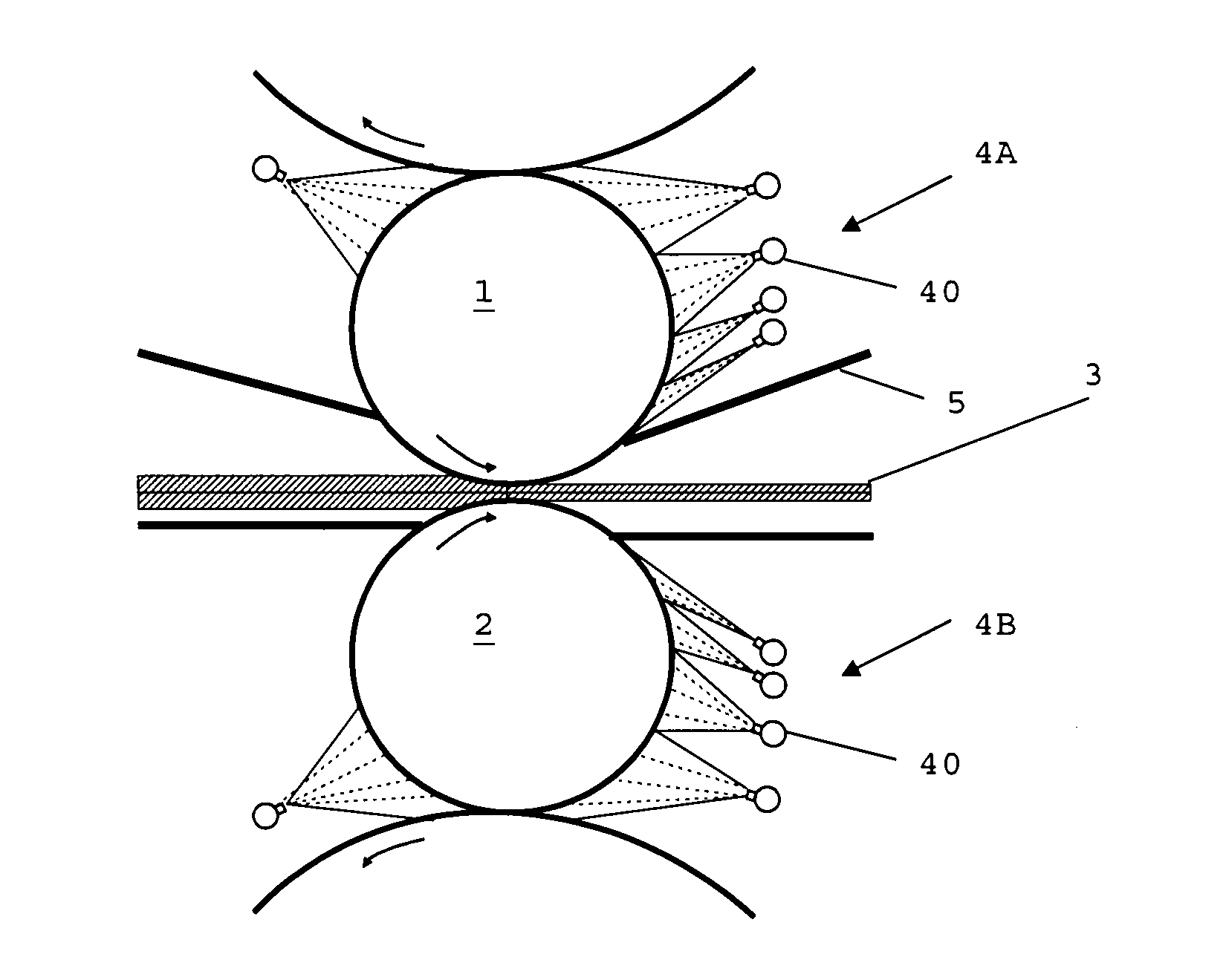
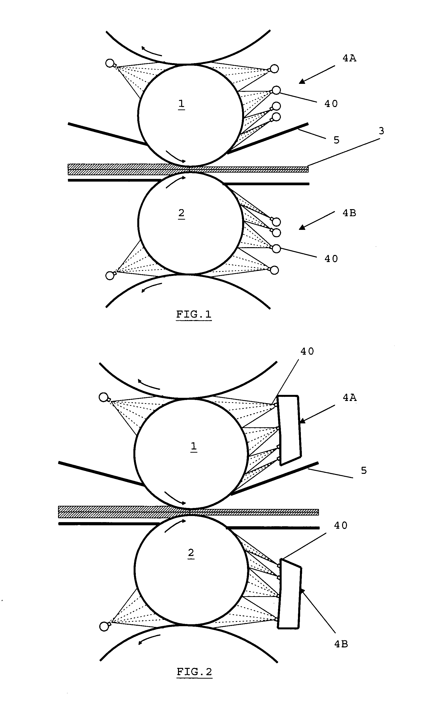
[0013]In particular, this invention aims to provide effective cooling of rolling cylinders whilst guaranteeing a reduction of thermo-mechanical fatigue and hence less deterioration in the surfaces of the cylinders.
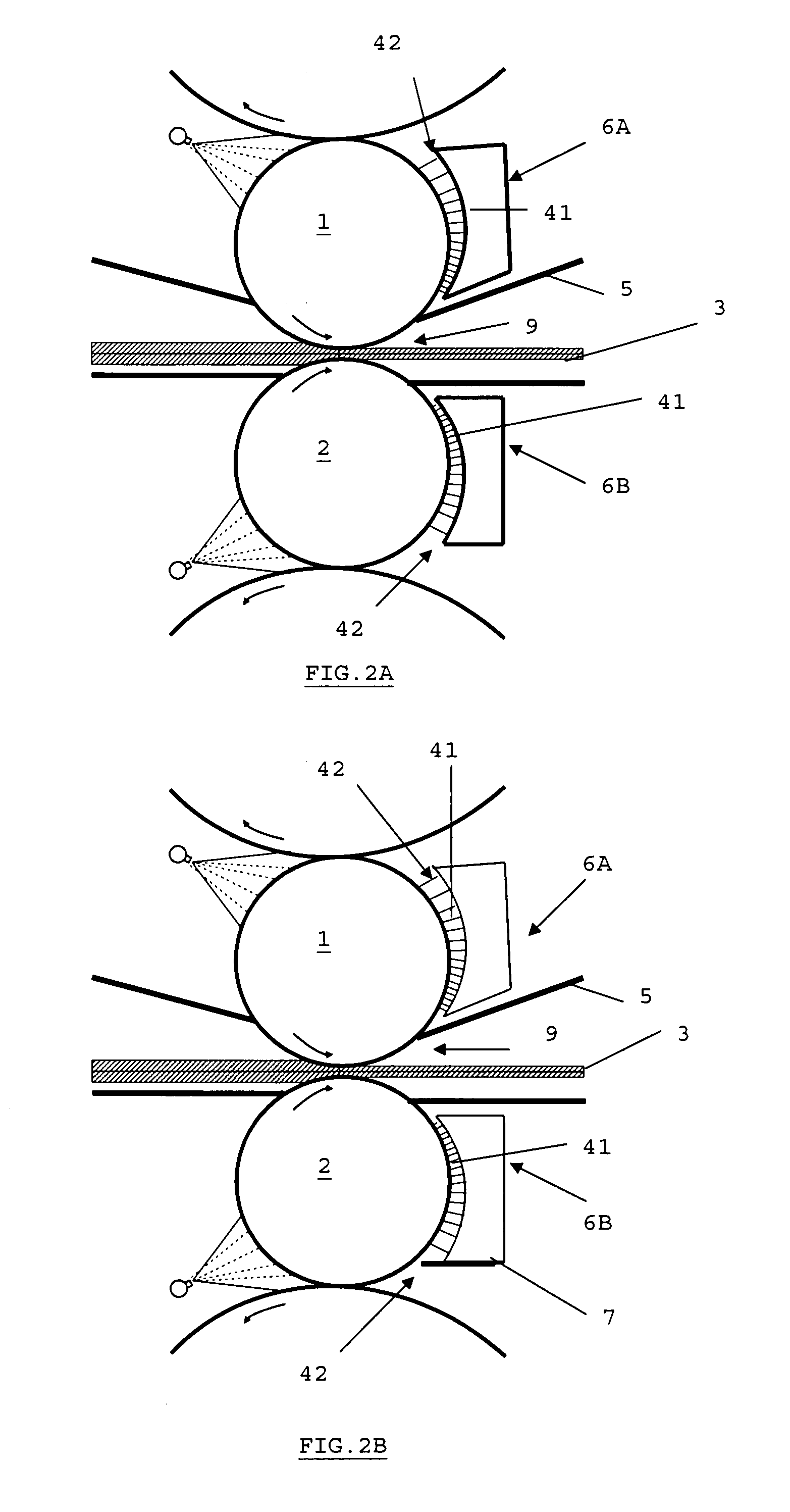
[0018]As an advantage, the cooling head is also equipped with adjustable side plates positioned at the side of the transverse ends of the cylinder and located at a distance from the cylinder in such a way that said side plates co-operate with the front of the box and with the transverse lower plate in order to ensure the control of the flow of liquid coolant and its confinement in the form of a highly turbulent water pillow.
[0019]As an advantage, the curve of the side plates matches the maximum curve of the cylinders used in the installation.

Problems solved by technology

In general, the distance between the nozzles and the cylinder is 150-500 mm, which does not allow to use cylinders of different diameters with one single cooling device.

Method used


Image

  • Device and Method for Cooling Rollers Used for Rolling in a Highly Turbulent Environment
  • Device and Method for Cooling Rollers Used for Rolling in a Highly Turbulent Environment
  • Device and Method for Cooling Rollers Used for Rolling in a Highly Turbulent Environment

Examples


Embodiment Construction

[0045]According to the invention, shown in FIGS. 2A to 2D, the cooling head is designed to implement WPC technology, i.e. with a view to create a pillow of highly turbulent water between the cooling head and the surface of the work roll. The turbulence is caused by spraying water at low pressure into the water pillow through nozzles with straight jets developed by the Applicant.

[0046]According to FIGS. 2A to 2D, the cooling installation as in the invention comprises an upper box 6A facing the upper roll 1 and a lower box 6B facing the lower roll 2. Each box 6A, 6B has a concave surface 42 opposite the corresponding roll 1,2. This concave surface 42 comprises a wall with several apertures of a specified size forming straight nozzles 41 and forming a specified pattern. The concave surface 42 may advantageously cover a larger part of the circumference in the case of the upper cylinder 1 than in the case of the lower cylinder 2.

[0047]The water pillow is formed in the gap restricted by t...


PUM

PropertyMeasurementUnit
Pressureaaaaaaaaaa
Pressureaaaaaaaaaa
Pressureaaaaaaaaaa

Abstract

(EN) The present invention relates to a device for cooling a working roll (1, 2) belonging to a rolling stand used for rolling a long or flat product (3), characterized in that it comprises a cooling head in the form of a box section (6A, 6B) that is sealed except along a front face (42) lying a short distance from said roll (1, 2), and in which face a plurality of nozzles (41) has been machined or positioned in a determined pattern, said box section (6A, 6B) being concave and cylindrical at its front face (42). The box section (6A, 6B) is also fitted with transverse (5, 7) and lateral (8) plates which collaborate with the front face (42) of the box section so as to control the flow of cooling liquid and confine said liquid in the form of a highly turbulent flow. This then yields optimal cooling of the roll both in terms of the uniformity of the cooling across the surface thereof and in terms of the reduction in temperature as a result of the turbulent effect created.

Description

FIELD OF THE INVENTION[0001]The present invention relates to a new method for cooling rolling cylinders (or rolls), possibly of variable diameter, based on a highly turbulent flow environment (high turbulence cooling, HTC). The method is called high turbulence work roll cooling (HTRC).[0002]The invention also relates to the device for implementing the method.TECHNOLOGICAL BACKGROUND AND STATE OF THE ART[0003]The heating of hot-rolling cylinders is due to the transmission of heat to the rolls by conduction from the product, such as a strip of metal, that is being rolled. In recent years, the cooling of rolling cylinders has been intensively studied because of its very large impact on the deterioration of said cylinders (wear) as a result of the thermomechanical fatigue generated and on the control of the curve of the cylinders. The deterioration of the cylinders has a very great impact on the quality of the product.[0004]A typical installation for cooling work cylinders in a rolling ...

Claims


Application Information

Patent Timeline
IPC IPC(8): B21B27/10B05B1/14
CPCB21B27/10B21B31/00B21B13/00
Inventor UIJTDEBROEKS, HUGOVAN POECKE, PATRICKVANDERSCHUEREN, DIRKNOVILLE, JEAN-FRANCOIS
Owner CENT DE RECH METALLURGIQUES CENT VOOR RES IN DE METALLURGIE
Learn More