

Seal-tight grommet and method of producing same
a technology of sealing device and grommet, which is applied in the direction of electrical equipment, etc., can solve the problems of limiting the use of the chamber to test benches and electronic devices, rendering the fixing of the cables to the wall of the chamber virtually final, and ensuring the seal-tightness of the chamber. simple and cost-effective
Inactive Publication Date: 2010-04-15
THALES SA
View PDF9 Cites 1 Cited by
- Summary
- Abstract
- Description
- Claims
- Application Information
AI Technical Summary
Benefits of technology
[0014]The invention notably has the advantage that it enables all types of conductor wires to pass between the outside and the inside of the chamber while simply and cost-effectively ensuring the seal-tightness of the chamber.
Problems solved by technology
The devices to be tested can also be subjected to radiations or vibrations.
This first solution presents several drawbacks, notably in terms of versatility and safety.
A first drawback results from the fact that the paste is applied more or less irretrievably, rendering the fixing of the cables to the wall of the chamber virtually final.
This virtually final fixing limits the use of the chamber to test benches and to electronic or microelectronic devices that are suited to the cables fixed to the chamber.
A second drawback results from the fact that the seal-tightness between the inside and the outside of the chamber depends on the way in which the paste is applied, notably between the cables or, where appropriate, between the conductor wires that make up the cables.
Consequently, the seal-tightness of the chamber is not guaranteed and risks posing problems for personnel in the vicinity of the chamber, notably when the chamber contains corrosive gases.
Although this solution presents advantages over the first solution, notably by simplifying the production of the seal-tightness of the orifice, it also presents drawbacks.
A first drawback is the limitation of the possible connections between the devices to be tested and the test bench via the electrical connector.
A second drawback is the degradation of the connection between the devices to be tested and the test bench, a degradation that is intrinsic to any insertion of electromechanical contacts.
This drawback is all the more significant in the field of microwave signals.
Method used
View moreImage
Smart ImageViewing Examples

Examples
first embodiment
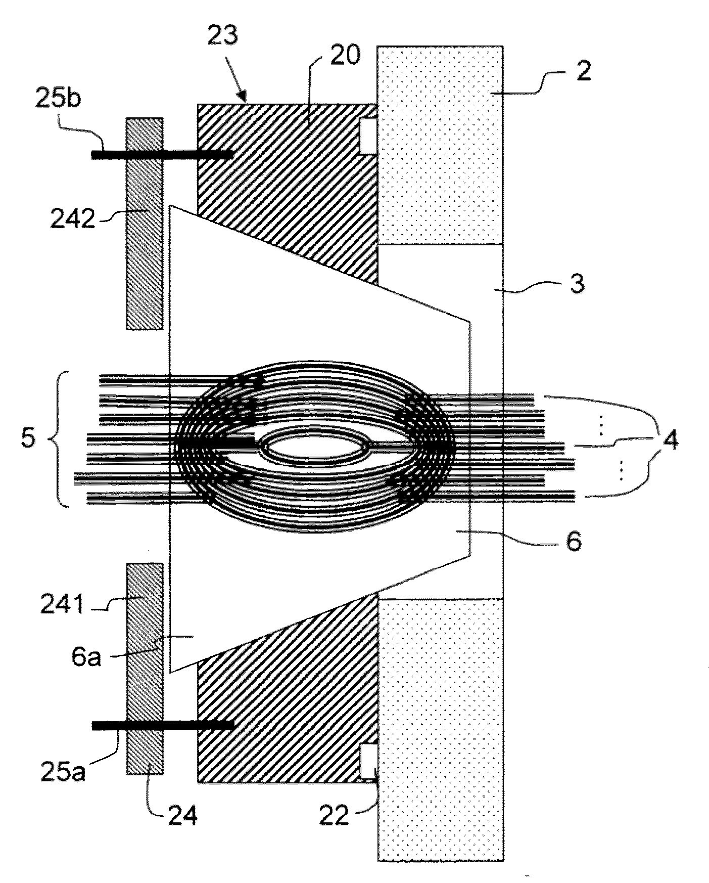
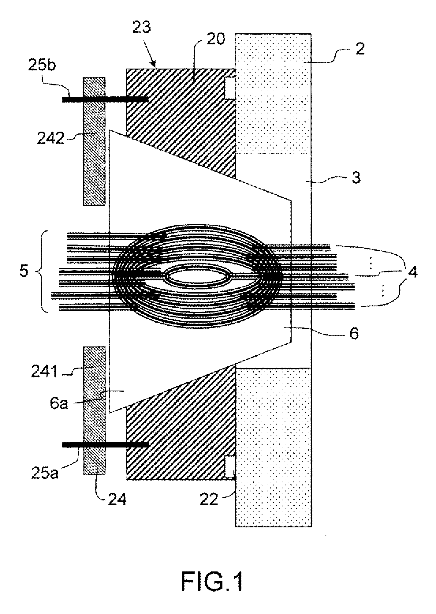
[0036] the relative spacing between the conductor wires 4 is maintained by beads 31 threaded around each conductor wire 4.
second embodiment
[0037] the relative spacing between the conductor wires 4 is obtained by a first step of clamping the conductor wires 4 at each end of the section where a plug 6 is to be formed and a second step of bringing the ends together to obtain an ovoid form of the strand 5.
[0038]According to a particular embodiment, the coating of the conductor wires 4 comprises a step of passing the conductor wires 4 through a mould, the internal form of which corresponds to that of the plug 6 and a step of injection of the elastic material into the mould.
Login to View More PUM
 Abstract
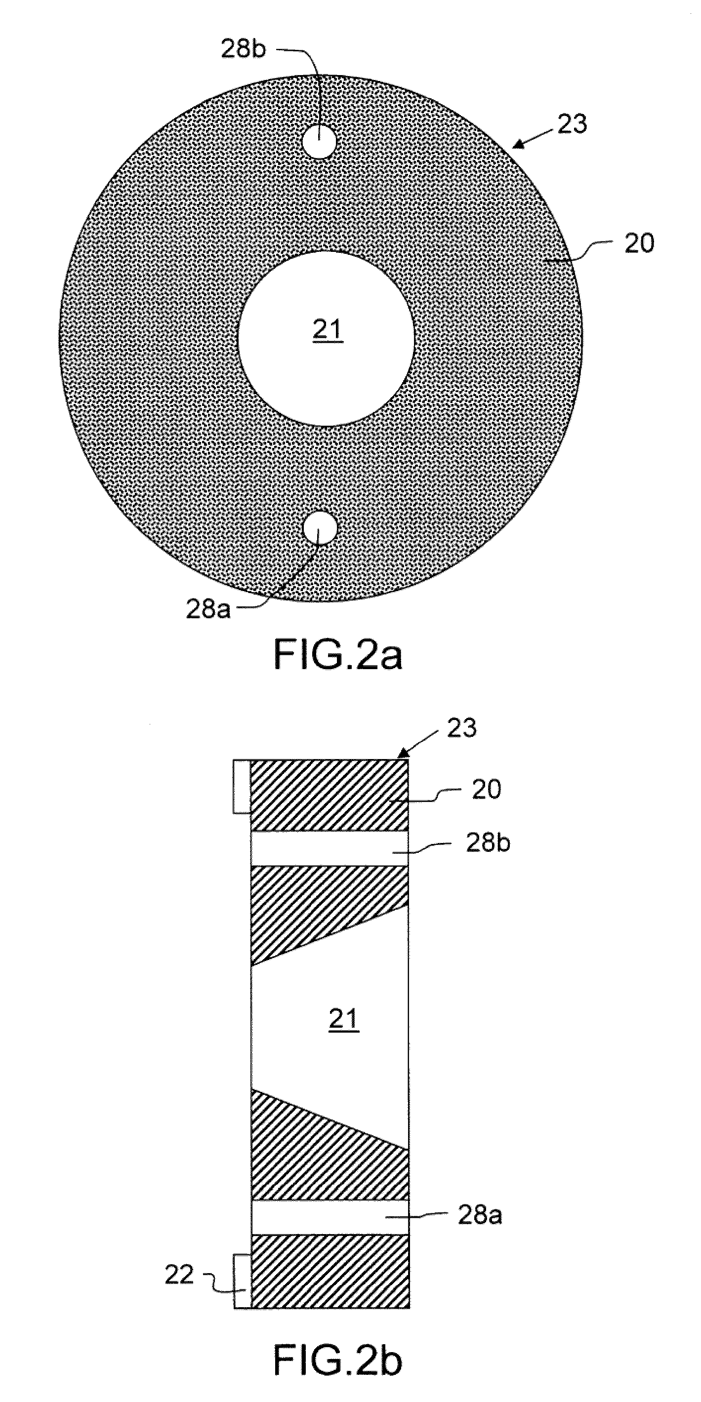
The invention relates to a sealing device for a chamber partition, the partition having an orifice enabling a strand of conductor wires to pass between the outside and the inside of the chamber. The device includes a plug through which passes the strand, and an apparatus to keep the plug pressed against the partition. The conductor wires can be kept away from one another inside the plug to ensure the seal-tightness of the plug itself. Advantageously, the plug is pressed into a void of a counter-form, the internal shape of the void substantially complementing an external shape of the plug. The form / counter-form assembly provides for a perfect seal-tightness.
Description
CROSS-REFERENCE TO RELATED APPLICATION[0001]The present application claims the benefit of French Patent Application 0802666, filed May 16, 2008, which is hereby incorporated by reference in its entirety.BACKGROUND OF THE INVENTION[0002]The present invention relates to a sealing device for a chamber partition, the partition comprising an orifice enabling a strand of conductor wires to pass between the outside and the inside of the chamber. Such a device is commonly called a grommet. The invention also relates to a sealing method for producing such a device.[0003]Chambers are used in many scientific and industrial areas to make it possible to work in a contained atmosphere. This is notably the case for the electronics and microelectronics industry for which environment tests are performed on electronic or microelectronic devices in particular physico chemical conditions. In the event, these devices can be tested in conditions of temperature, of pressure and of medium that differ from ...
Claims
Login to View More Application Information
Patent Timeline
 Patent Type & AuthorityApplications(United States)
IPC IPC(8): H02G3/18
CPCH02G3/22
InventorBOUSQUET, PATRICKMANAC'H, XAVIERDESCOURS, PHILIPPE
OwnerTHALES SA