Friction-assisted tube fabrication method

a technology of friction-assisted tube and fabrication method, which is applied in the field of friction-assisted tube fabrication method, can solve the problems of inability to apply conventional processes and methods in an industrial scale, the limitation of processing metal objects, and the increase of equipment and high processing force and power, so as to achieve easy softening, simple increase the radius of the tube, and the effect of softening the deformation area

Inactive Publication Date: 2021-03-11
HOSSEINI SEYYED HADI +1
View PDF0 Cites 1 Cited by
  • Summary
  • Abstract
  • Description
  • Claims
  • Application Information

AI Technical Summary

Benefits of technology

[0016]One aspect of the present disclosure is directed to a method for friction assisted forming a metal object into a tube, comprising: a) forcing the metal object with an initial radius across the slope of a mandrel with an angle; and b) rotating the mandrel while forcing the metal object to deform into a tube with a desired radius, wherein the tube is in contact with the slope of the mandrel while rotating, thereby generating thermal energy to heat a deformation area of the tube for simply and easily softening and forming into a desired shape with a desired value of radius and dimensions using a nominal pressing force.
[0017]In one embodiment the metal object is a deformable tube. In another embodiment, the mandrel is configured to simply increase the radius of the tube by heating and softening the deformation area using thermal energy generated by friction between the tube and the slope of the mandrel while rotating. In one embodiment, the radius of the tube is decreased using a die. In another embodiment, the die is configured to slidably and rotatably secure to an external surface of the tube. In one embodiment, the die is further configured to rotate in a clockwise direction or a counterclockwise direction or with rotational oscillations. In one embodiment, the die is further configured to enable an operator to rapidly rotate over the deformation area of the external surface of the tube, thereby generating thermal energy due to friction between the external surface and the die to heat the deformation area for simply and easily softening and precisely decreasing the tube radius to a desired value using a nominal pressing force.
[0018]Another aspect of the present disclosure is directed to a method for friction assisted extruding a tube, comprising forcing the tube with an initial thickness across the slope of an inner mandrel; and securing a die over an external surface of the tube and rapidly rotating the die over a deformation area of the tube, thereby generating thermal energy due to friction between the external surface and the die to heat the deformation area of the tube for simply and easily softening and precisely decreasing the tube thickness to a desired value using a nominal pressing force.
[0019]In one embodiment, the inner mandrel is configured to securely hold the tube during the friction assist extruding process. In another embodiment, the die is configured to slidably and rotatably secure to an external surface of the tube. In one embodiment, the die is further configured to rotate in a clockwise direction or a counterclockwise direction or with rotational oscillations. In another embodiment, the die is further configured to enable an operator to rapidly rotate over

Problems solved by technology

Although many strengthening methods have been developed in the last years, all of them have limitations to process metal objects, for example, elongated members and tube products because it requires more equipment and high processing force and power.
Therefore, conventional processes and methods cannot be applied in an industrial scale.
When the accuracy of the dimensions is inferior and more largely deviated and as a result, the fatigue strength of the metal object, for example, a pipe or a tube, is extremely decreased.
In addition, the smoothness of an interior surface and an exterior surface of the metal object, for example, a pipe or a tube is not satisfactory, and as a result, irregularities are liable to remain thereon.
However, the conventional metal forming methods requires high power and multiple equipment thus increases the cost for forming metal objects.
In addition, there is no forming

Method used


Image

  • Friction-assisted tube fabrication method
  • Friction-assisted tube fabrication method
  • Friction-assisted tube fabrication method

Examples


Embodiment Construction

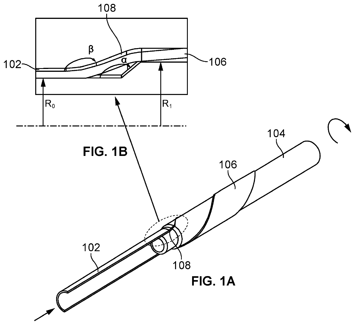
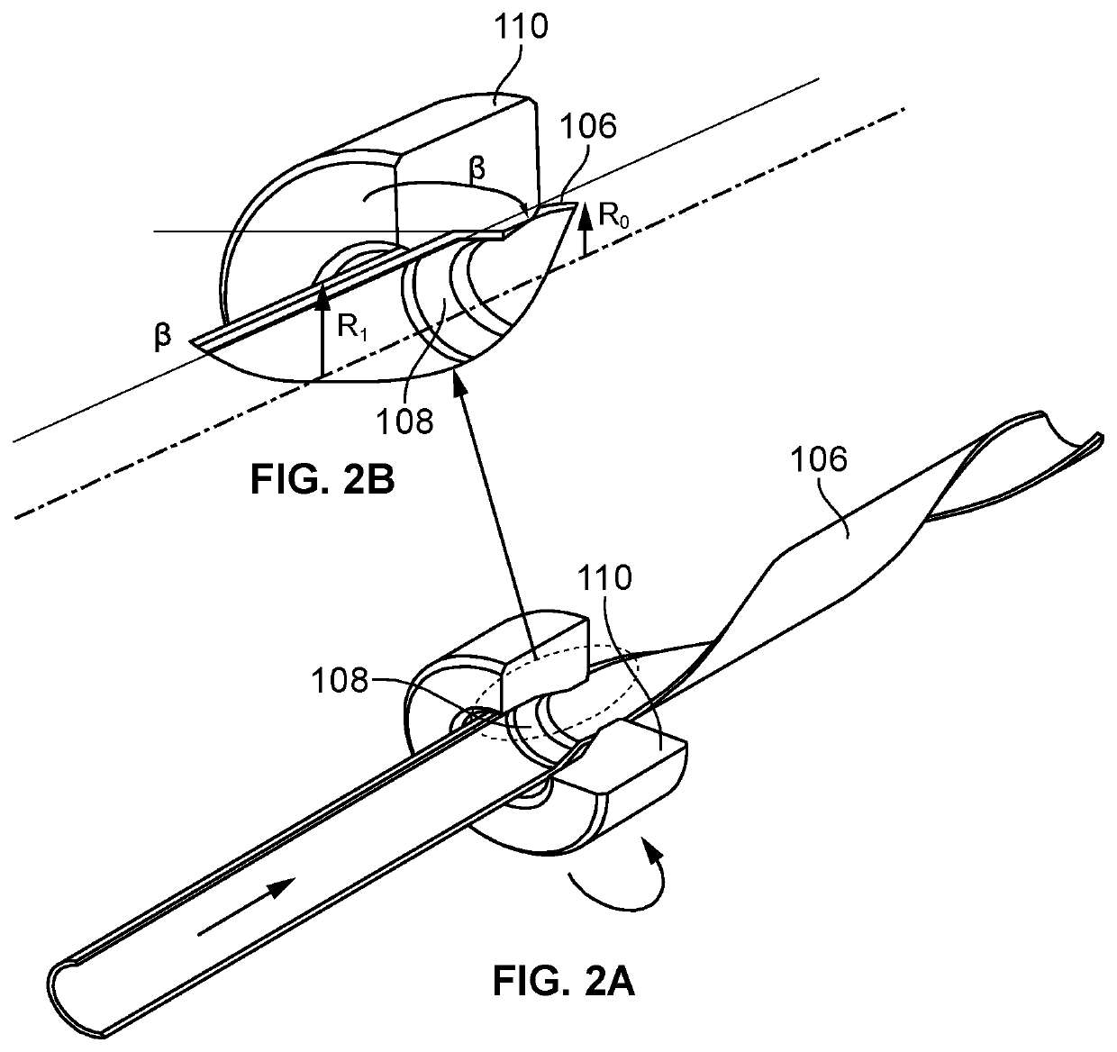
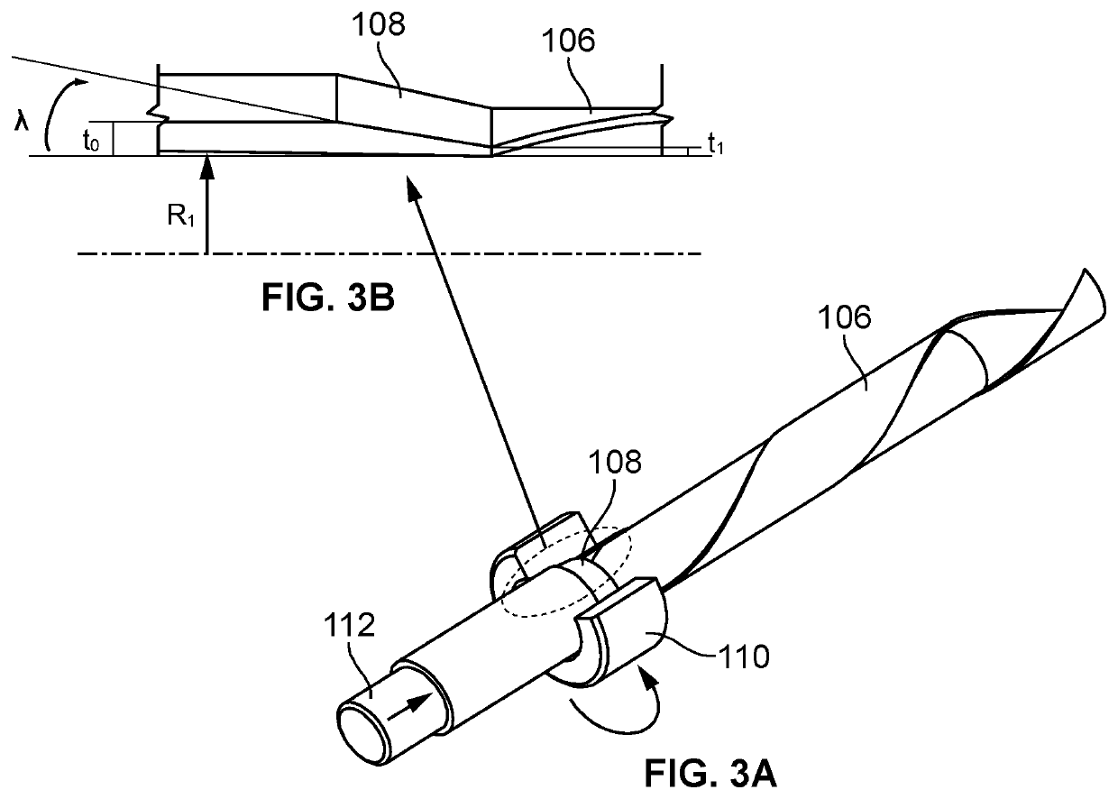
[0030]The present invention generally relates to a method for fabricating elongated members and tubular products and more particularly relates to a friction-assisted tube fabrication method used to produce high-strength elongated members and tubular products, wherein the friction-assisted tube fabrication method includes a set of processes or methods such as a friction assisted tube forming method, a friction assisted tube extrusion / extruding method, and a friction assisted tube straining method.

[0031]A description of embodiments of the present invention will now be given with reference to the figures. It is expected that the present invention may be embodied in other specific forms without departing from its spirit or essential characteristics. The described embodiments are to be considered in all respects only as illustrative and not restrictive. The scope of the invention is, therefore, indicated by the appended claims rather than by the foregoing description. All changes that co...


PUM

PropertyMeasurementUnit
Thicknessaaaaaaaaaa
Diameteraaaaaaaaaa
Radiusaaaaaaaaaa

Abstract

A friction assisted tube fabrication method is disclosed. The friction assisted tube fabrication includes a set of methods such as a friction assisted tube forming, a friction assisted tube extrusion, and a friction assisted tube straining method. A metal object, for example, a deformable tube is simply deformed into the tube using a mandrel. The metal object with an initial diameter is forced across the slope of the mandrel with an angle. The mandrel is configured to rotate while forcing the metal object to deform into the tube with the desired radius. While rotating the mandrel, a friction is generated due to contact between the tube and the mandrel, thereby generating thermal energy to heat a deformation area of the tube for simply and easily softening and forming into the desired shape with accuracy diameter, and dimensions using a nominal pressing force without additional equipment and power.

Description

BACKGROUND OF THE INVENTION[0001]Metal forming is a metalworking process of fashioning metal parts and objects through mechanical deformation. A workpiece or a material is reshaped without adding or removing material. Forming operates on the materials science principle of plastic deformation, where the physical shape of a material is permanently deformed. Currently, applications of high strength material in various industries have been expanding. Although many strengthening methods have been developed in the last years, all of them have limitations to process metal objects, for example, elongated members and tube products because it requires more equipment and high processing force and power. Therefore, conventional processes and methods cannot be applied in an industrial scale.[0002]In addition, the formed metal objects should have mechanical properties and desirable dimensions such as an inner diameter, an outer diameter, and a thickness with high accuracy. When the accuracy of th...

Claims


Application Information

Patent Timeline
IPC IPC(8): B21C23/20B21C23/08B21C23/21
CPCB21C23/205B21C23/211B21C23/085B21C1/22B21C1/24B21C1/26
Inventor HOSSEINI, SEYYED HADISEDIGHI, MOHAMMAD
Owner HOSSEINI SEYYED HADI
Why Eureka
Try Eureka