Manufacturing method of butt joint, butt joint, manufacturing method of bent member, and friction stir joining method

a manufacturing method and technology of a butt joint, applied in the direction of manufacturing tools, non-electric welding apparatuses, workpiece edge portions, etc., can solve the problem that the bending cannot be performed as intended, and achieve the effect of reducing high temperature deformation resistan

Inactive Publication Date: 2006-07-13
HONDA MOTOR CO LTD +1
View PDF1 Cites 14 Cited by
  • Summary
  • Abstract
  • Description
  • Claims
  • Application Information

AI Technical Summary

Benefits of technology

[0022] In the first aspect of the present invention, by setting the rotational direction of the probe of the joining tool so as to coincide with a rotational direction rotating from one of the joining members having a lower high temperature deformation resistance toward the other of the joining members having a higher high temperature deformation resistance at the back side of the joining direction, the joining member of lower high temperature deformation resistance is located at the treating side. Therefore, the joining member is easily softened, resulting in an increased rear surface stir region width (i.e., the width of the rear surface of the joined portion). As a result, even in cases where gaps are formed in the abutting portion of the joining members, the gaps can be assuredly filled with the materials of the joining members, which in turn can improve the joint strength of the obtained butt joint. Furthermore, since the rear surface stir region width increases, even if the probe insertion is not positioned accurately to the abutting portion at the time of joining, the abutting portion can be joined in a good manner, resulting in an improved joining operation.
[0023] In the present invention, the comparison of the high temperature deformation resistance of the joining members is performed based on the deformation resistance at the joining temperature. Concretely, in cases where both the joining members are made of aluminum or its alloy, the comparison is preferably performed based on the mean deformation resistance within the range of 200 to 600° C., more preferably 400 to 550° C. In this case, the rear surface stir region width can be increased assuredly.

Problems solved by technology

Accordingly, in cases where this butt joint is used as, for example, a bending material, the bending cannot be performed as intended.

Method used


Image

  • Manufacturing method of butt joint, butt joint, manufacturing method of bent member, and friction stir joining method
  • Manufacturing method of butt joint, butt joint, manufacturing method of bent member, and friction stir joining method
  • Manufacturing method of butt joint, butt joint, manufacturing method of bent member, and friction stir joining method

Examples


example 1

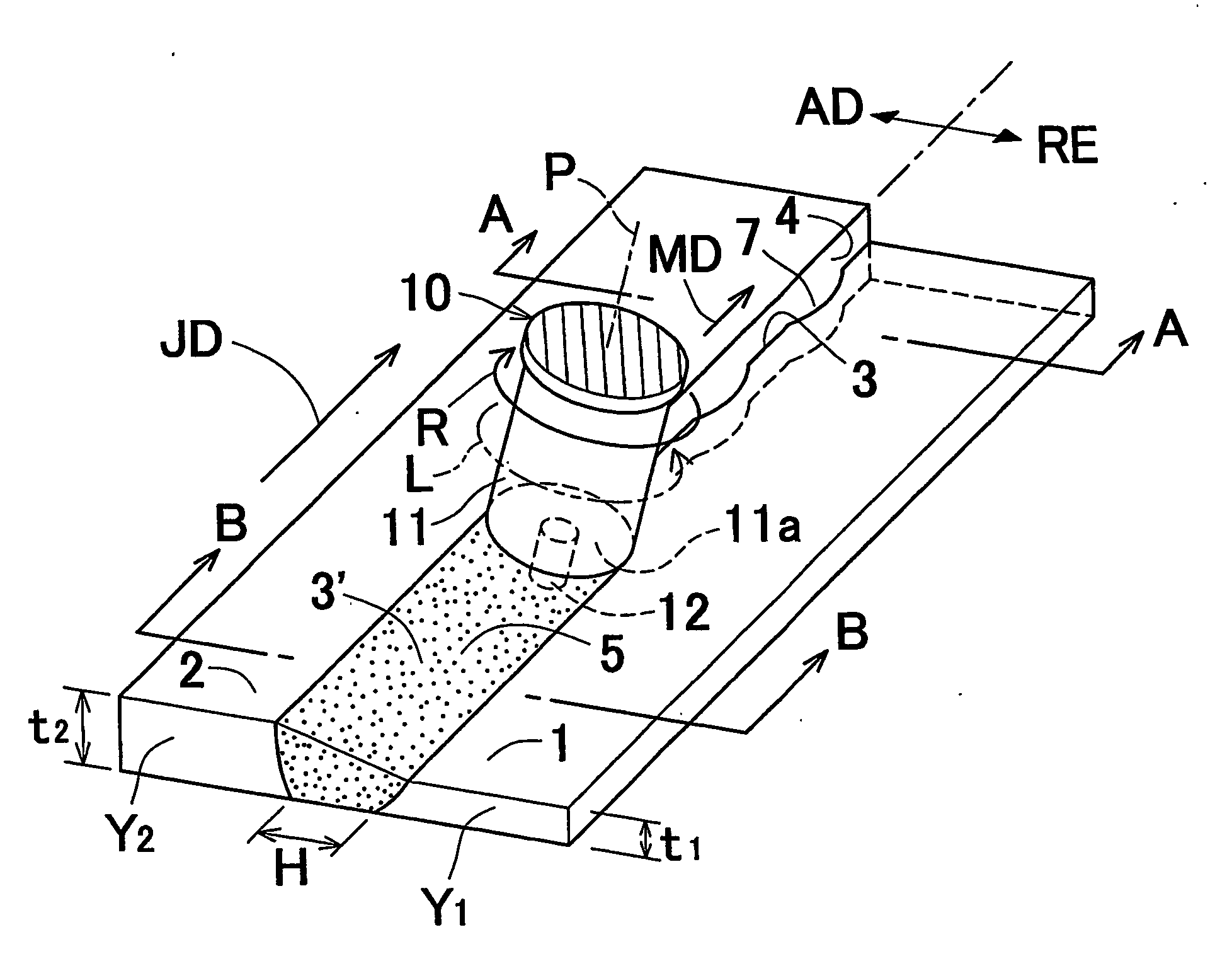
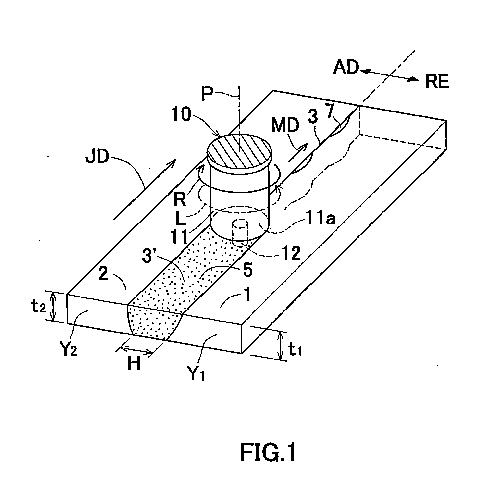
[0118] A flat plate-shaped aluminum alloy first joining member(JIS-A6061-T6, thickness t1=2 mm) and a flat plate-shaped aluminum alloy second joining member (JIS-A5083-O, thickness t2=2 mm) were prepared.

[0119] It is generally known that the mean deformation resistance of A6061-T6 in the temperature range of 400 to 550° C. is lower than that of A5083-O in the same temperature range. Accordingly, in the aforementioned temperature range, the product of the high temperature deformation resistance Y1 and the thickness T1 of the first joining member 1, i.e., the value (Y1×t1), is smaller than the product of the high temperature deformation resistance Y2 and the thickness t2 of the second joining member 2, i.e., the value (Y2×t2) (i.e., (Y1×t1)2×t2)).

[0120] On the other hand, as a joining tool 10, a joining tool having an end surface 11a of a rotor 11 whose diameter is 12 mm and a probe 12 having a diameter of 5 mm was prepared.

[0121] The aforementioned joining members 1 and 2 were dis...

example 2

[0125] A flat plate-shaped aluminum alloy first joining member(JIS-A5052-O, thickness t1=1 mm) and a flat plate-shaped aluminum alloy second joining member (JIS-A5052-O, thickness t2=2 mm) were prepared.

[0126] Since the material of the first joining member 1 and that of the second joining member 2 are the same, the value (Y1×t1) of the first joining member 1 was smaller than the value of (Y2×t2) (i.e., (Y1×t1)2×t2)).

[0127] The aforementioned joining members 1 and 2 were disposed in an abutted manner with the rear surfaces thereof flush with each other. Then, the rotational direction of the rotor 11 of the joining tool 10 and that of the probe 12 were set so as to coincide with the rotational direction R rotating from the first joining member 1 toward the second joining member 2 at the back side of the joining direction JD. Then, in accordance with the joining procedures shown in the second embodiment, the abutting portion 3 of the joining members 1 and 2 was joined. As the joining...


PUM

PropertyMeasurementUnit
temperatureaaaaaaaaaa
diameteraaaaaaaaaa
diameteraaaaaaaaaa

Abstract

Two joining members different in high temperature deformation resistance are disposed in an abutted manner. The rotational direction of a probe of a joining member is set to coincide with a rotational direction rotating from the joining member having lower high temperature deformation resistance toward the joining member having higher high temperature deformation resistance. Then, the rotating probe is inserted into the abutting portion of the joining members. The probe is advanced along the abutting portion with the probe inserted in the abutting portion to perform friction stir joining. As a result, a butt joint having high joining strength can be obtained.

Description

CROSS REFERENCE TO RELATED APPLICATIONS [0001] This application is an application filed under 35 U.S.C. §111(a) claiming the benefit pursuant to 35 U.S.C. § 119(e) (1) of the filing date of Provisional Application No. 60 / 470,502 filed on May 15, 2003 pursuant to 35 U.S.C. §111(b).[0002] Priority is claimed to Japanese Patent Application No. 2002-198457, filed on Jul. 8, 2002 and U.S. Provisional Patent Application No. 60 / 470,502, filed on May 15, 2003, the disclosure of which are incorporated by reference in their entireties. TECHNICAL FIELD [0003] The present invention relates to a manufacturing method of a butt joint to be used as a metal member for use in transportation apparatuses, electrical household appliances, industrial machinery or the like, and also to such a butt joint. The present invention also relates to a friction stir joining (welding) method preferably used for manufacturing the butt joint and a manufacturing method of a bent member. BACKGROUND ART [0004] The follo...

Claims


Application Information

Patent Timeline
Patent Type & Authority Applications(United States)
IPC IPC(8): B23K20/12B23K31/02B23K20/233B23K33/00
CPCB23K20/122B23K20/123B23K20/2336B23K33/004
Inventor AKIYAMA, HIROSHINARITA, MASAYUKINAGANO, YOSHITAKAHASHIMOTO, TAKENORI
Owner HONDA MOTOR CO LTD
Why Eureka
Try Eureka