Test apparatus and test method

a test apparatus and test method technology, applied in the field of test apparatus and test method, can solve the problems of transmission line loss or similar loss, and differ in the amount of jitter caused by transmission line loss or the lik

Inactive Publication Date: 2010-04-15
ADVANTEST CORP
View PDF11 Cites 12 Cited by
  • Summary
  • Abstract
  • Description
  • Claims
  • Application Information

AI Technical Summary

Benefits of technology

[0008]Therefore, it is an object of an aspect of the innovations herein to provide a test apparatus and a test method, which are capable of overcoming the above drawbacks accompanying the related art. The above and other objects can be achieved by combinations described in the independent claims. The dependent claims define further advantageous and exemplary combinations of the innovations herein.
[0009]According to a first aspect related to the innovations herein, one exemplary test apparatus may include a test apparatus that tests a device under test, comprising a pattern generating section that generates a test pattern determined according to a test signal to be supplied to the device under test; a timing signal generating section that generates a timing signal indicating a timing for supplying the test signal to the device under test; a digital filter that filters the test pattern to output a jitter control signal representing jitter corresponding to the test pattern; a jitter injecting section that injects the timing signal with jitter by delaying the timing signal according to the jitter control signal; and a waveform shaping section that generates the test signal formed according to the test pattern, with the timing signal into which the jitter is injected as a reference.
[0010]According to a second aspect related to the innovations herein, one exemplary test apparatus may include a test apparatus that tests a device under test, comprising a signal output section that outputs a test signal to the device under test; a signal input section that receives an output signal from the device under test output in response to the test signal; a pattern generating section that generates an expected value pattern determined according to the output signal to be output from the device under test; a timing signal generating section that generates a strobe signal indicating a timing for comparing the expected value pattern and the output signal; a digital filter that filters the expected value pattern to ...

Problems solved by technology

Known types of jitter that are added to a signal transmitted between devices include jitter caused by transmission line loss, jitter caused by inter-symbol interferen...

Method used


Image

  • Test apparatus and test method
  • Test apparatus and test method
  • Test apparatus and test method

Examples


Embodiment Construction

[0025]Hereinafter, some embodiments of the present invention will be described. The embodiments do not limit the invention according to the claims, and all the combinations of the features described in the embodiments are not necessarily essential to means provided by aspects of the invention.

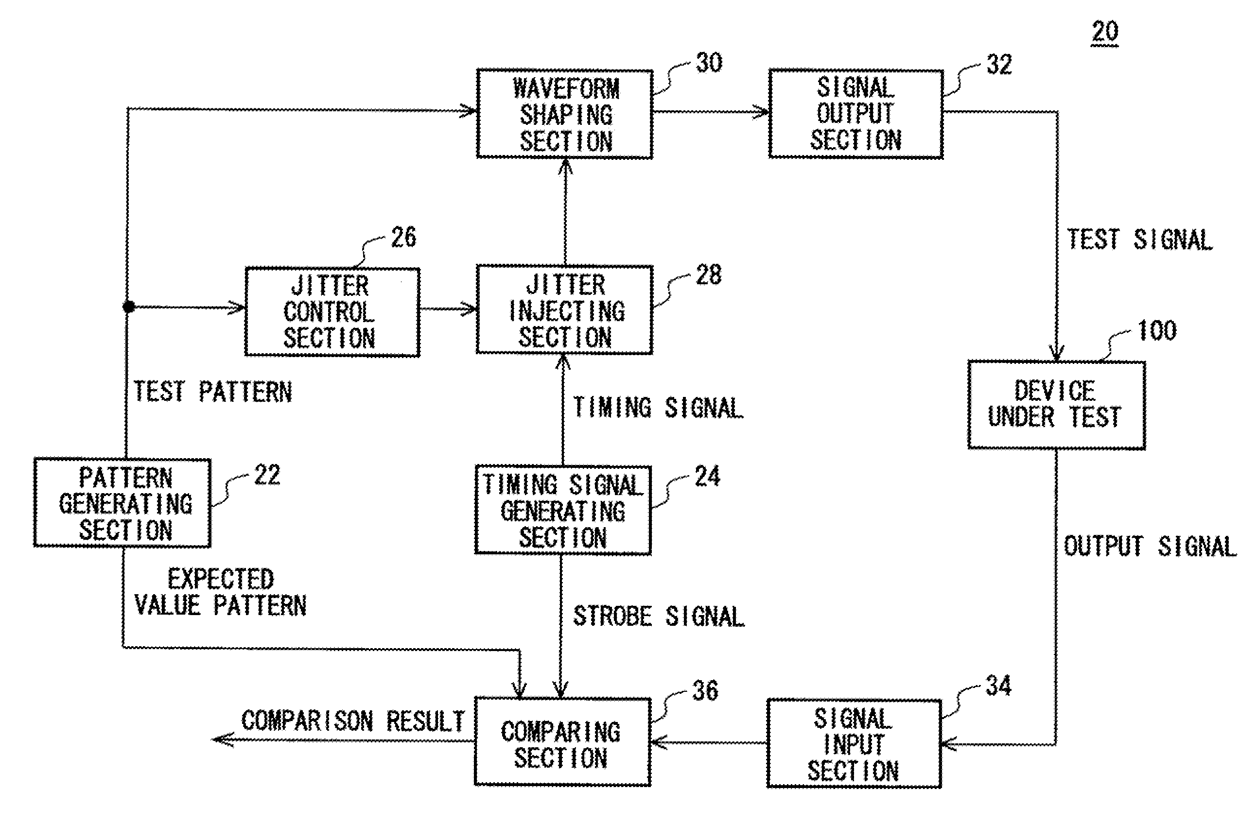
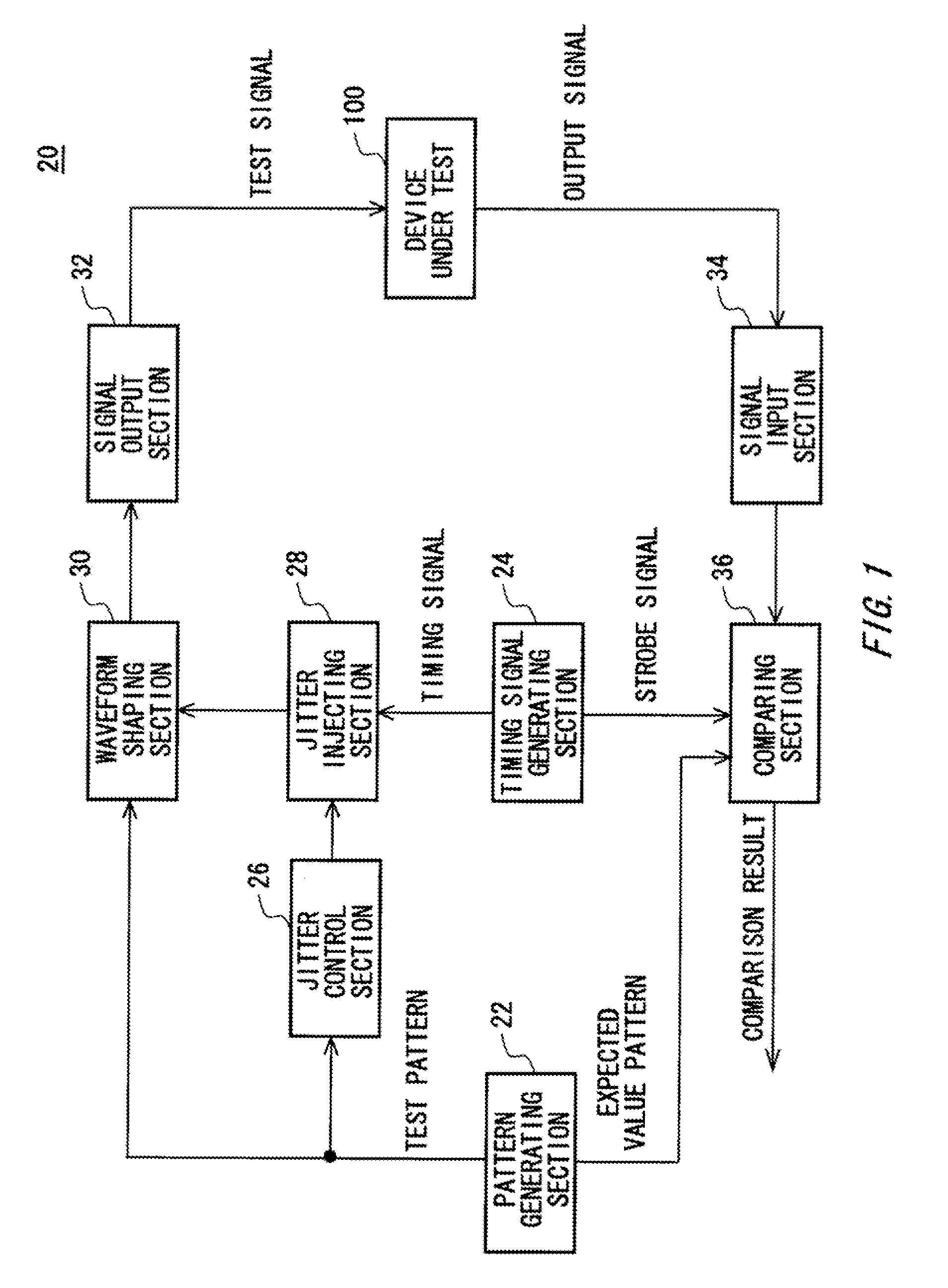
[0026]FIG. 1 shows a configuration of a test apparatus 20 according to an embodiment of the present invention, along with a device under test 100. The test apparatus 20 tests the device under test 100 by outputting a test signal into which jitter is injected to the device under test 100 and making a comparison between an output signal from the device under test 100 output in response to the test signal and an expected value. The test apparatus 20 is provided with a pattern generating section 22, a timing signal generating section 24, a jitter control section 26, a jitter injecting section 28, a waveform shaping section 30, a signal output section 32, a signal input section 34, and a comparing s...


PUM


Abstract

Provided is a test apparatus that tests a device under test, comprising a pattern generating section that generates a test pattern determined according to a test signal to be supplied to the device under test; a timing signal generating section that generates a timing signal indicating a timing for supplying the test signal to the device under test; a digital filter that filters the test pattern to output a jitter control signal representing jitter corresponding to the test pattern; a jitter injecting section that injects the timing signal with jitter by delaying the timing signal according to the jitter control signal; and a waveform shaping section that generates the test signal formed according to the test pattern, with the timing signal into which the jitter is injected as a reference.

Description

CROSS REFERENCE TO RELATED APPLICATION[0001]This is a continuation application of PCT / JP2008 / 057710 filed on Apr. 21, 2008 which claims priority from a Japanese Patent Application NO. 2007-114637 filed in JP on Apr. 24, 2007, the contents of which are incorporated herein by reference.BACKGROUND[0002]1. Technical Field[0003]The present invention relates to a test apparatus and a test method. In particular, the present invention relates to a test apparatus and a test method for testing a device under test by supplying the device under test with a test signal into which jitter is injected.[0004]2. Related Art[0005]A test apparatus that tests performance relating to jitter of a device under test is known, as in, for example, Japanese Patent Application Publication No. 2005-91108. This test apparatus is provided with a jitter injecting section that injects jitter into a test signal supplied to a device under test, and a jitter injection control section that generates a digital control si...

Claims


Application Information

Patent Timeline
IPC IPC(8): H01H31/02
CPCG01R29/26G01R31/31709H03K5/156G01R31/31937H03K3/84G01R31/31917G01R29/02G01R31/3183
Inventor WATANABE, DAISUKEOKAYASU, TOSHIYUKI
Owner ADVANTEST CORP
Why Eureka
Try Eureka