Image processing system, image processing apparatus, aberration correction method, and computer-readable storage medium

a technology of image processing and aberration correction, applied in image enhancement, instruments, computing, etc., can solve the problems of pin-cushion-shaped images, red, blue and green color bleeding at the boundary of object images, and the inability to maintain the high image quality of an image to be displayed. to achieve the effect of reducing coordinate conversion errors

Active Publication Date: 2010-04-15
CANON KK
View PDF4 Cites 43 Cited by
  • Summary
  • Abstract
  • Description
  • Claims
  • Application Information

AI Technical Summary

Benefits of technology

[0022]The present invention provides a technique which can reduce coordinate conversion errors even when the size of a table used in coordinate conversion of pixels is reduced upon correction of image forming position deviations caused by aberrations.

Problems solved by technology

When an optical system is configured using inexpensive lenses or by suppressing the number of lenses, high image quality of an image to be displayed cannot often be maintained due to lens aberration.
That is, barrel- or pin-cushion-shaped images are often obtained due to distortion aberrations of lenses.
Also, red, blue, and green color bleeding appears at the boundaries of object images due to chromatic aberrations of magnification of lenses.
However, the size of a reference table which stores the correspondence with the coordinates after conversion depends on the size of an original image and the conversion precision, and the table size also becomes extreme in recent high-resolution and high-image quality trends.
If decimation is made to have an interval more than 16 pixels, errors at the time of interpolation increase.
However, the aforementioned related techniques suffer the following problems.
For this reason, it is expected to become increasingly difficult to reduce the table size while maintaining or improving the conversion precision.
This means that the bicubic interpolation is not suited to interpolating image forming position deviations, which change smoothly.

Method used


Image

  • Image processing system, image processing apparatus, aberration correction method, and computer-readable storage medium
  • Image processing system, image processing apparatus, aberration correction method, and computer-readable storage medium
  • Image processing system, image processing apparatus, aberration correction method, and computer-readable storage medium

Examples


first embodiment

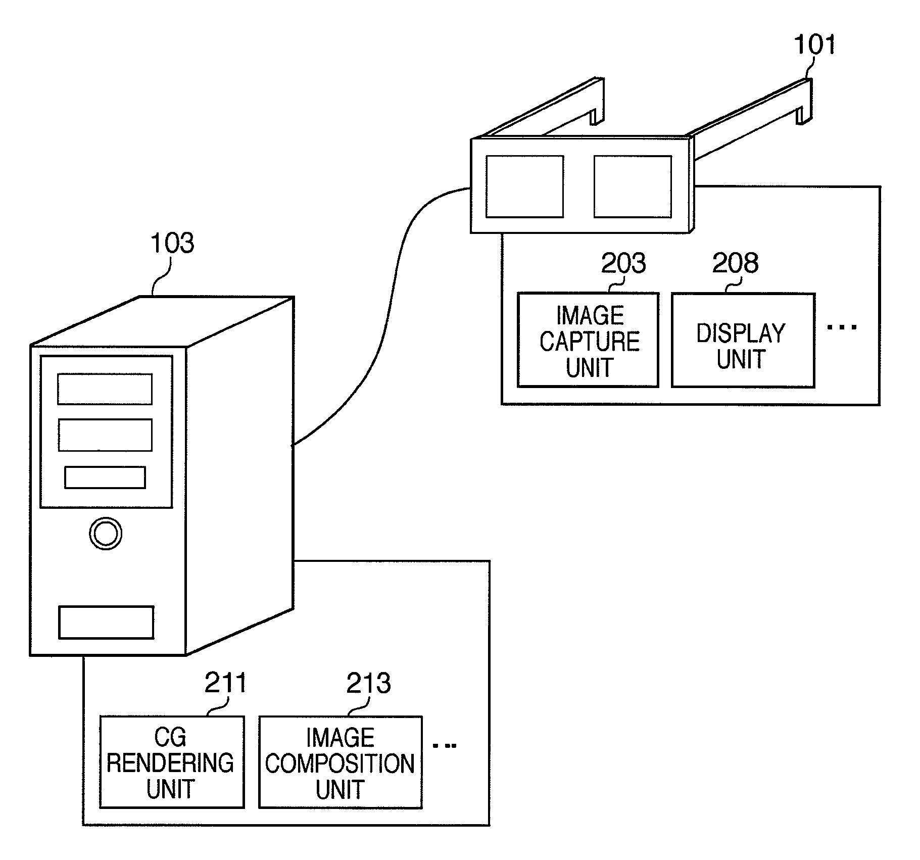
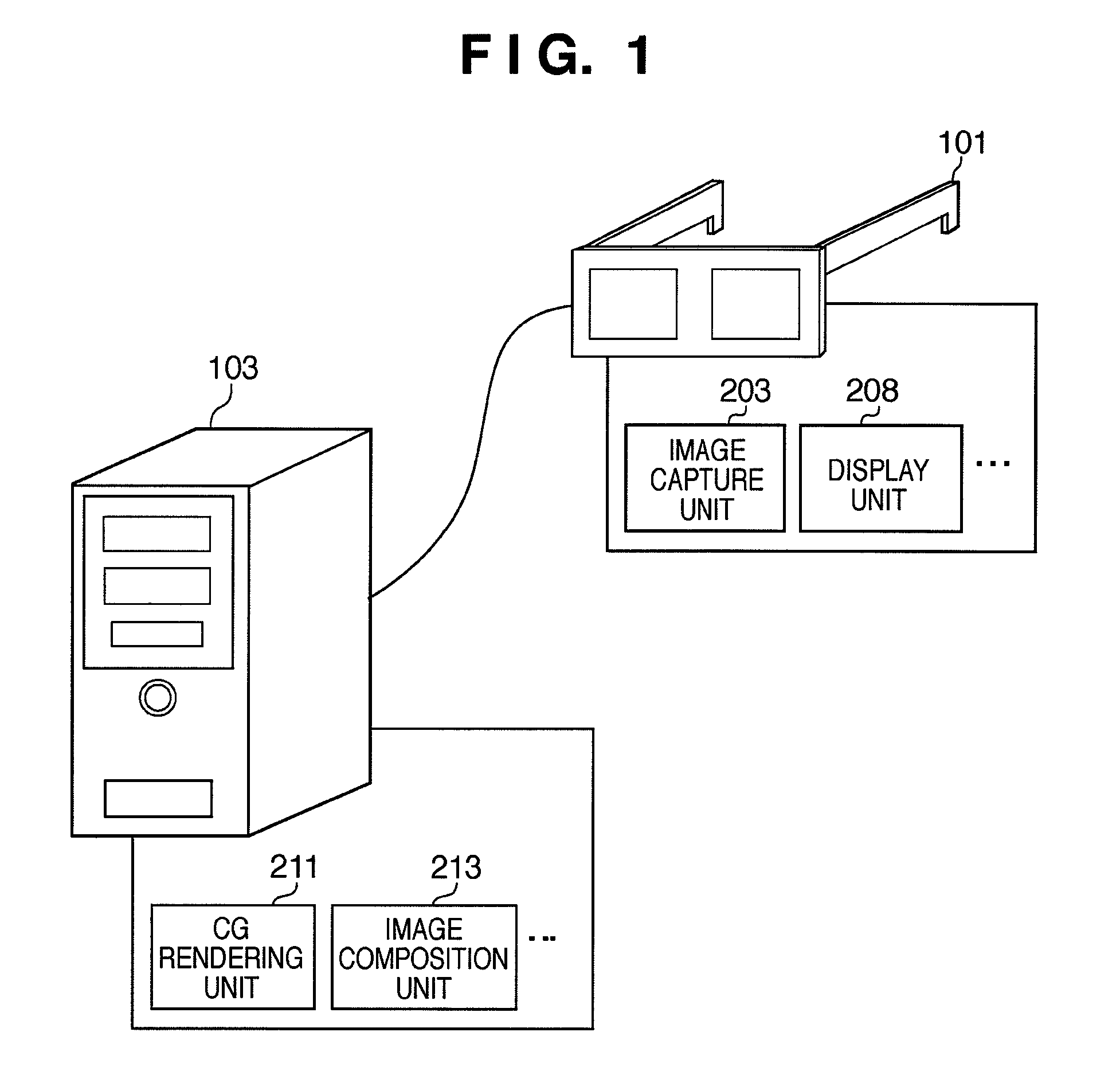
[0050]FIG. 1 is a view showing an example of the overall arrangement of an MR system.

[0051]Mixed reality, that is, a so-called MR technique, is known as a technique for seamlessly blending physical and virtual worlds in real time. The MR technique uses a display apparatus with an image capture function (to be referred to as an HMD hereinafter).

[0052]The HMD superimposes a CG image, which is generated based on three-dimensional position and orientation information including the position and direction of the user, on a background image of a physical space at the viewpoint of the user, which is acquired by its image capture unit 203, and displays a composite image on a display unit 208. As a result, the HMD user can experience mixed reality as if an object rendered by CG were existing on the physical space observed by the user. Note that FIG. 1 shows a head mounted type HMD, but the present invention is not limited to this. For example, a hand-held type display apparatus such as binocu...

second embodiment

[0155]The second embodiment will be described below. Note that the apparatus arrangement of the second embodiment is the same as that shown in FIGS. 1 to 5 used to describe the first embodiment. Hence, a description thereof will not be repeated, and a difference will be described below. The difference lies in that the interpolation processing at the time of coordinate conversion and pixel interpolation processing are configured as independent functional blocks in the first embodiment, while a common interpolation processing functional block is used in the second embodiment.

[0156]FIG. 18 is a block diagram showing an example of the functional arrangement in an aberration correction LSI 408 according to the second embodiment. Note that the same reference numerals in FIG. 18 denote the same components as in the functional arrangement shown in FIG. 9 used to explain the first embodiment, and a description thereof will not be repeated.

[0157]The aberration correction LSI 408 includes a bu...


PUM


Abstract

An image processing system, which corrects an aberration generated in an optical system by executing coordinate conversion of pixels of an image, has a table which holds correspondence between the positions of pixels before and after the coordinate conversion, acquires coordinates after conversion corresponding to the coordinates of representative points to be converted from the table, and calculates coordinates after conversion of a pixel between the acquired representative points by an interpolation calculation using a Lagrange interpolation formula.

Description

BACKGROUND OF THE INVENTION[0001]1. Field of the Invention[0002]The present invention relates to an image processing system, image processing apparatus, aberration correction method, and computer-readable storage medium, which correct aberrations of an optical system.[0003]2. Description of the Related Art[0004]In recent years, as a technique for seamlessly blending physical and virtual worlds in real time, a so-called MR (Mixed Reality) technique is known. As one MR technique, a technique using a video see-through HMD (Head Mounted Display; to be hereinafter abbreviated as an HMD) is known. With this technique, an object which nearly matches an object observed from the pupil position of an HMD user is captured using, for example, a video camera, and CG (Computer Graphics) is superimposed on that captured image. Then, the HMD user can observe an MR image.[0005]The video see-through HMD acquires digital image data of an object by capturing an image of that object using a charge coupl...

Claims


Application Information

Patent Timeline
Patent Type & Authority Applications(United States)
IPC IPC(8): G09G5/00G06K9/32G06K9/00
CPCG06T5/006
Inventor TSUJIMOTO, TAKUYA
Owner CANON KK
Why Eureka
Try Eureka