Photo Sensor Array Using Controlled Motion

a technology of photo sensor array and controlled motion, which is applied in the direction of color signal processing circuit, television system scanning details, television system, etc., can solve the problem that the dynamic range of the human eye still falls far shor

Inactive Publication Date: 2010-04-15
IBM CORP
View PDF12 Cites 20 Cited by
  • Summary
  • Abstract
  • Description
  • Claims
  • Application Information

AI Technical Summary

Problems solved by technology

While this matches or exceeds the dynamic range of film based technologies, it still falls far short of the dynamic range of the human eye.

Method used


Image

  • Photo Sensor Array Using Controlled Motion
  • Photo Sensor Array Using Controlled Motion
  • Photo Sensor Array Using Controlled Motion

Examples


Embodiment Construction

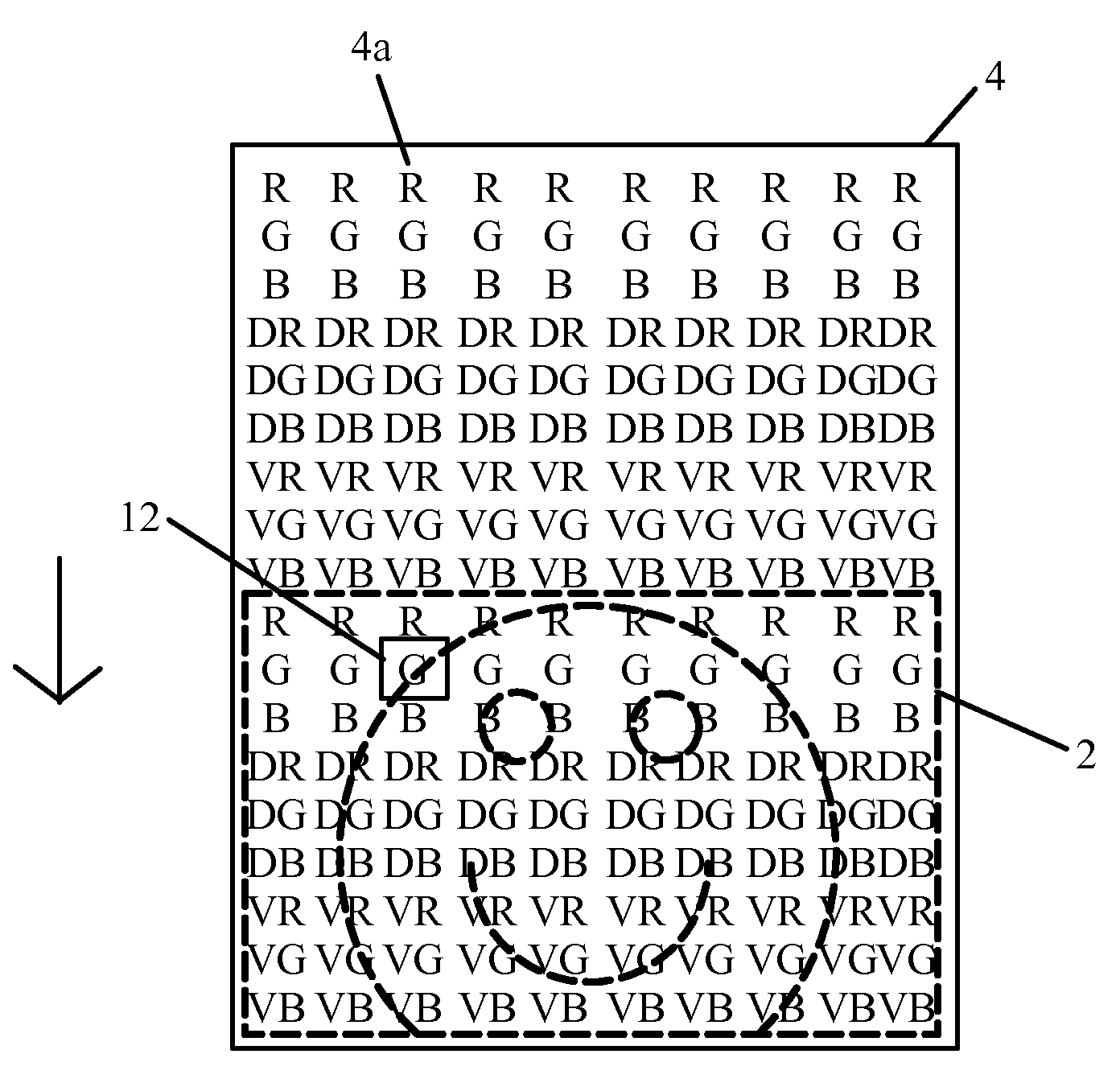
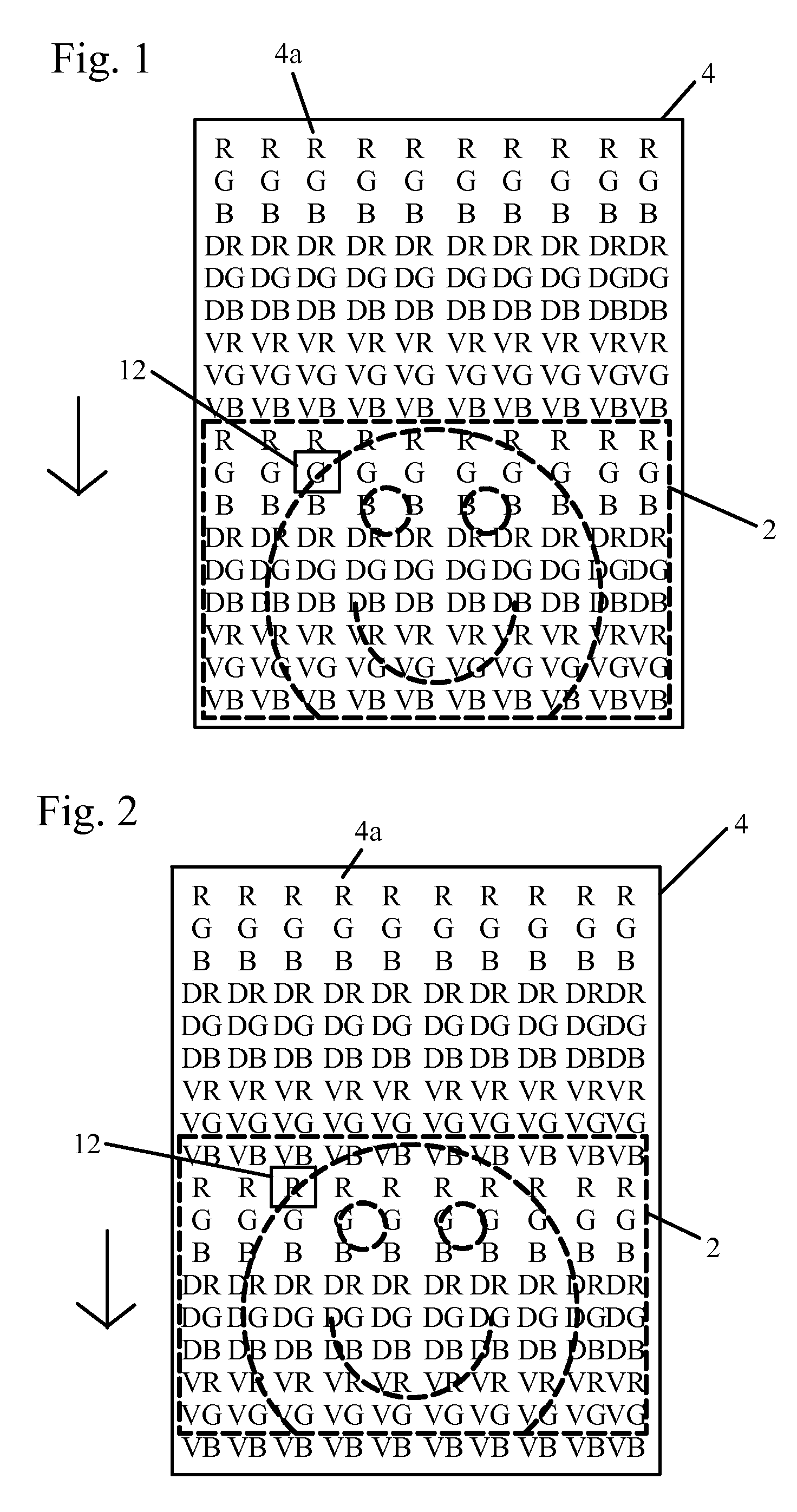
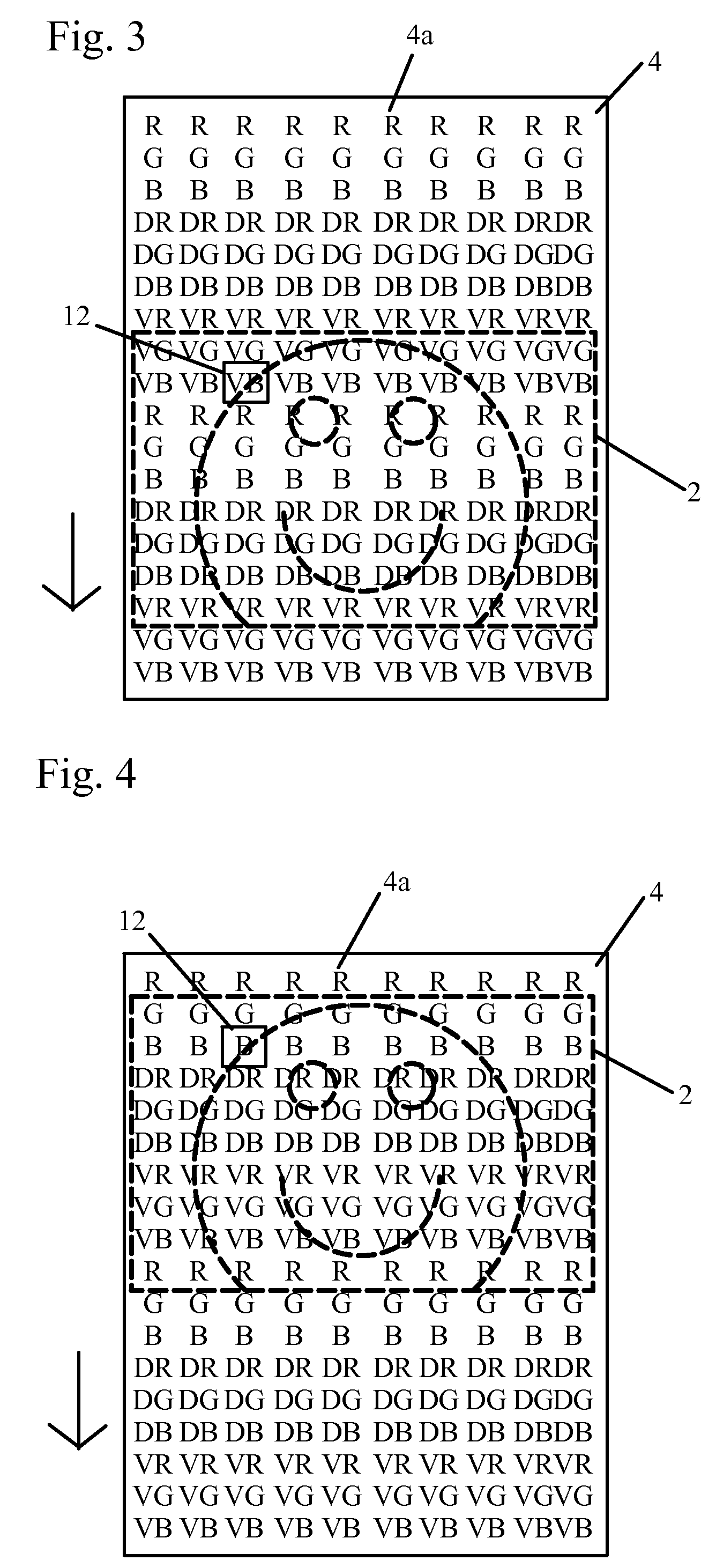
[0010]FIGS. 1-4 show an embodiment of the present invention using a moving photo sensor 4. A photo sensor 4 has an array in which each of the columns 4a linearly records red R, green G, and blue B information. Neutral density filters are added to each of the columns 4a across a range of neutral density values to change the exposure values for individual pixel sites without changing the color values. In other words, the neutral density filters make each site less sensitivity to light without adding any color casts. For example, each column 4a of the photo sensor has a pixel site for red R, green G, and blue B, with dark filters denoted as dark red DR, dark green DG, and dark blue DB, and with very dark filters denoted as very dark red VR, very dark green VG, and very dark blue VB.

[0011]A single column 4a of pixel sites of all three color values with filters on the photo sensor array are recorded across a range of exposure values. The pixel sites with the lowest neutral density filter...


PUM


Abstract

A movable sensor including a plurality of photo pixel sites arranged in an array comprising a photo sensor and a neutral density filter filtering the photo sensor. Each of the neutral density filters have a density value that are graduated over a range of densities. The sensor is linearly movable across an image. Each point in the image is exposed to at least one pixel site with the graduated density values and each of the photo pixel sites of the array is exposed to a same light input during a time span of exposure, such that the image is captured at a defined range of exposure values and can be combined into a single high dynamic range image.

Description

BACKGROUND OF THE INVENTION[0001]The present invention relates to photo sensor arrays, and more specifically to photo sensor arrays using controlled motion and graduated filters to capture high dynamic range images.[0002]Current image capture devices used in consumer and professional digital photography rely on sensors that have a relatively low dynamic range, currently ranging up to about 11 EV. While this matches or exceeds the dynamic range of film based technologies, it still falls far short of the dynamic range of the human eye. High dynamic range images allow for the capture of images that more closely match the human perception of a scene, as well as allowing for non-destructing photo image manipulation.[0003]Two existing techniques exist for capturing high dynamic images. First, a dedicated high dynamic range photo sensor can be used. These sensors generally trade resolution for dynamic range. Software exists for merging multiple low resolution images into a high dynamic ran...

Claims


Application Information

Patent Timeline
Patent Type & Authority Applications(United States)
IPC IPC(8): H04N5/228
CPCH04N5/35563H04N9/045H04N5/35572H04N25/585H04N25/587H04N25/134H04N25/57
Inventor HABLUTZEL, ROBERT P.
Owner IBM CORP
Why Eureka
Try Eureka