Mobile network, mobile network base station and method to register a mobile terminal on a network

Inactive Publication Date: 2010-04-15
KONINK KPN NV
View PDF0 Cites 25 Cited by
  • Summary
  • Abstract
  • Description
  • Claims
  • Application Information

AI Technical Summary

Benefits of technology

[0050]The present invention aims to alleviate the above-mentioned problems. Particularly, the invention provi

Problems solved by technology

It occurs that those methods have severe drawbacks in terms of cost and customer impact.
Various disadvantages arise from the national roaming solution:The main problem is to get PLMN 1 cleared of the forbidden PLMN list of subscribers of network 2.
It is possible to use an Over The Air transmission (OTA) (particularly to update the FPLMN list), but this is not possible for the entire subscriber base.
It is also possible to have the subscribers manually select network 1, but this disadvantageously burdens and thus negatively impacts the customer.Brand names (of network operators) in the display of mobile terminals are not guaranteed or not guaranteed to be correct (see below conce

Method used


Image

  • Mobile network, mobile network base station and method to register a mobile terminal on a network
  • Mobile network, mobile network base station and method to register a mobile terminal on a network
  • Mobile network, mobile network base station and method to register a mobile terminal on a network

Examples


first embodiment

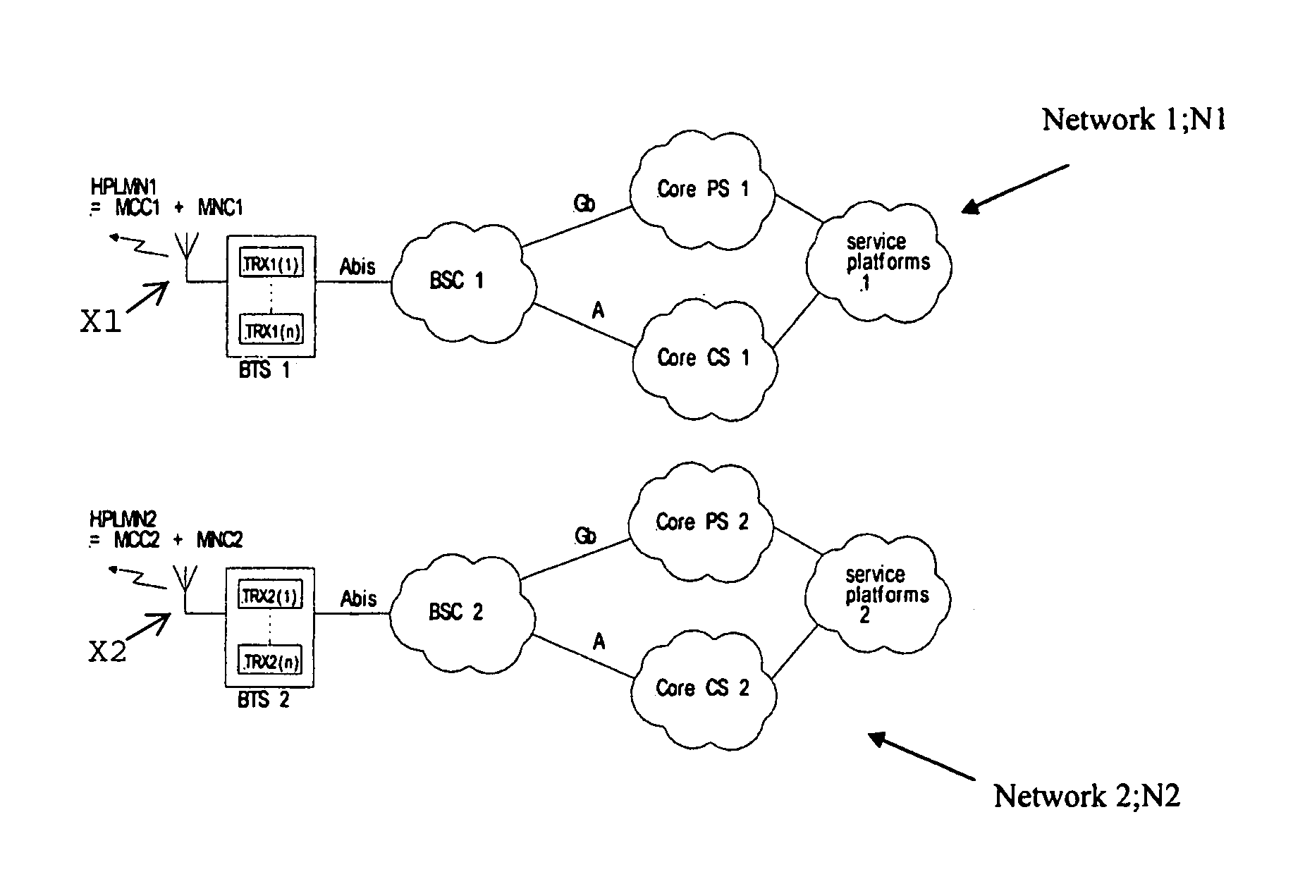
[0122]According to an embodiment of the invention, the inventive concept relies on configuring at least one separate first transmitter-receiver (TRX1) (and preferably each) in the base station BTS1 of the first network to such an extent that first transmitter-receiver behaves on the first radio interface / antenna X1 as would a transceiver TRX2 of the second network. This is shown in FIG. 5. Also, more TRXs may be configured as second network TRXs, however at least one of those TRXs is preferably configured as BCCH TRX (broadcast channel TRX). This BCCH TRX continuously transmits pilot channels and broadcast channels during its operation, and amongst the PLMN code. Via this TRX, terminals UE are also able to register in the network.

[0123]Specifically, FIG. 5 shows an embodiment of the present invention having a (single) mobile network configured to broadcast a first network identity HPLMN1 and a (different) second network identity HPLMN2 to provide a first and a second network layer. ...

second embodiment

[0161]FIG. 6 shows a second embodiment of the invention which differs from the embodiment of FIG. 5 in that a second Core CS (“Core CS 2”) is provided and which is coupled to the first Core CS (“Core CS 1”) and to second network service platforms (“service platforms 2”).

[0162]The second embodiment can be called a “Separate core network variant”. In case a two-layer architecture is used to discard one network, e.g., a second network (Network 2), that architecture can migrate all service platforms from the old core network 2 to the remaining network 1. To circumvent this problem, in the alternative architecture according to FIG. 6, a route to the remaining core network 2 is added. All traffic, based on IMSI can be directed to core network 2.

[0163]For PS (Packet Switched), the need to do so is not high so it is rather simple to add APNs and migrate service platforms connected to PS network 2 to PS network 1.

third embodiment

[0164]FIG. 7 shows a third embodiment of the invention, which differs from the embodiment shown in FIG. 5 in that a third network layer is provided which relates to a (previous) third network. For example, in FIG. 7, one or more additional third transceivers TRX3 (of the first Base Station) are provided and configured to broadcast a third network identity HPLMN3 (including a third MCC and a third MNC), preferably, again, via the same radio interface and utilizing the same base station controller BSC1. Thus, this yields a three-layer architecture.

[0165]As follows from FIG. 7, the concept with two layers (see FIGS. 5 and 6) can be extended with additional layers, simply by configuring transceivers to accommodate more layers. Practical restrictions could occur which heavily depend on base station type and the traffic volumes for each layer.

[0166]Traffic Steering: Mutual Use of Resources Between Layers

[0167]Introduction

[0168]Illustratively, two separate and independent layers are create...


PUM


Abstract

A mobile network, configured to broadcast at least a first network identity and a second network identity, particularly to provide a first and a second network layer. Also, a method is provided to register a mobile terminal on a network, having the steps of broadcasting, via the network the first and second network identities; receiving the network identities and registering the mobile terminal on the network when a received network identity corresponds with an individual mobile subscriber identity (IMSI) of a respective subscriber of the terminal.

Description

BACKGROUND OF THE INVENTION[0001]1. Field of the Invention[0002]The invention relates to a mobile network. The invention also relates to a mobile network base station, to a method to register a mobile terminal on a network, a method to provide a mobile network and the use of such method.[0003]2. Description of the Prior Art[0004]In the present application, it is assumed that the skilled reader has some common general knowledge with regard to mobile network technology. This application uses various acronyms, all of which are defined at the end of the application. The following concepts as such are assumed to be known to the skilled reader:[0005]General architecture of mobile networks in terms of core network elements like MSC, GMSC, SGSN, GGSN, HLR, etc., radio network elements like BSC and base stations and transmission between network elements;[0006]General functionality of mobile networks with regard to mobility features;[0007]General accepted terminology in mobile network technol...

Claims


Application Information

Patent Timeline
IPC IPC(8): H04W8/06H04W4/00H04W48/18H04W60/00
CPCH04W60/00H04W48/18
Inventor VERHOEF, DIRK ANTOINEKLEPPER, MATTHIJSVAN NULAND, THEODORUS JOHANNES PETER
Owner KONINK KPN NV
Why Eureka
Try Eureka