
Motherboard system, storage device for booting up thereof and connector

a technology for motherboards and storage devices, applied in the field of motherboard systems, can solve the problem that the update of the booting program cannot be accomplished, and achieve the effect of convenient updating and maintaining the system rom and the booting program

Active Publication Date: 2010-04-15
PHISON ELECTRONICS
View PDF18 Cites 10 Cited by
  • Summary
  • Abstract
  • Description
  • Claims
  • Application Information

AI Technical Summary

Benefits of technology

[0008]Accordingly, the present invention is related to a motherboard system, by which a removable system ROM can be accessed via an industry standard interface card, so as to conveniently update and maintain the system ROM and a booting program.
[0009]The present invention is directed to a flash memory storage device, which can provide a system ROM required for booting the aforementioned motherboard system in a removable approach, so as to conveniently update and maintain the system ROM and a booting program.
[0013]In the present invention, since the removable system ROM is applied, and is connected to the motherboard system via the industry standard interface card, the booting program in the system ROM can be effectively updated and maintained.

Problems solved by technology

However, as size and complexity of the booting program (for example, the BIOS) are continually increased, while the hardware is also frequently updated, the booting program has to be continually updated for supporting the new hardware.
Though embodying the system ROM by the EPROM can facilitate the user to update the booting program while the hardware is updated, in the conventional technique, the EPROM is still fixedly disposed on the motherboard system, so that when a storage capacity thereof is not enough to store the updated booting program, updating of the booting program cannot be accomplished.

Method used


Image

  • Motherboard system, storage device for booting up thereof and connector
  • Motherboard system, storage device for booting up thereof and connector
  • Motherboard system, storage device for booting up thereof and connector

Examples


Embodiment Construction

[0019]The accompanying drawings are included to provide a further understanding of the invention, and are incorporated in and constitute a part of this specification. The drawings illustrate embodiments of the invention and, together with the description, serve to explain the principles of the invention.

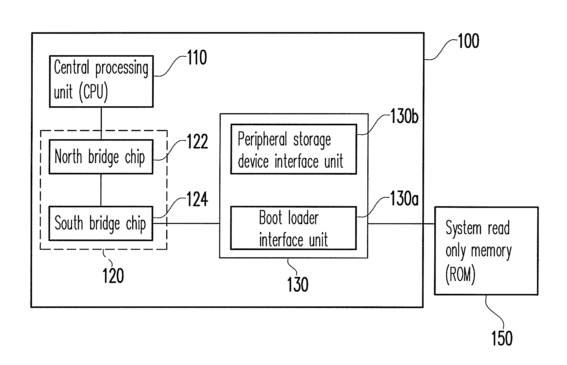
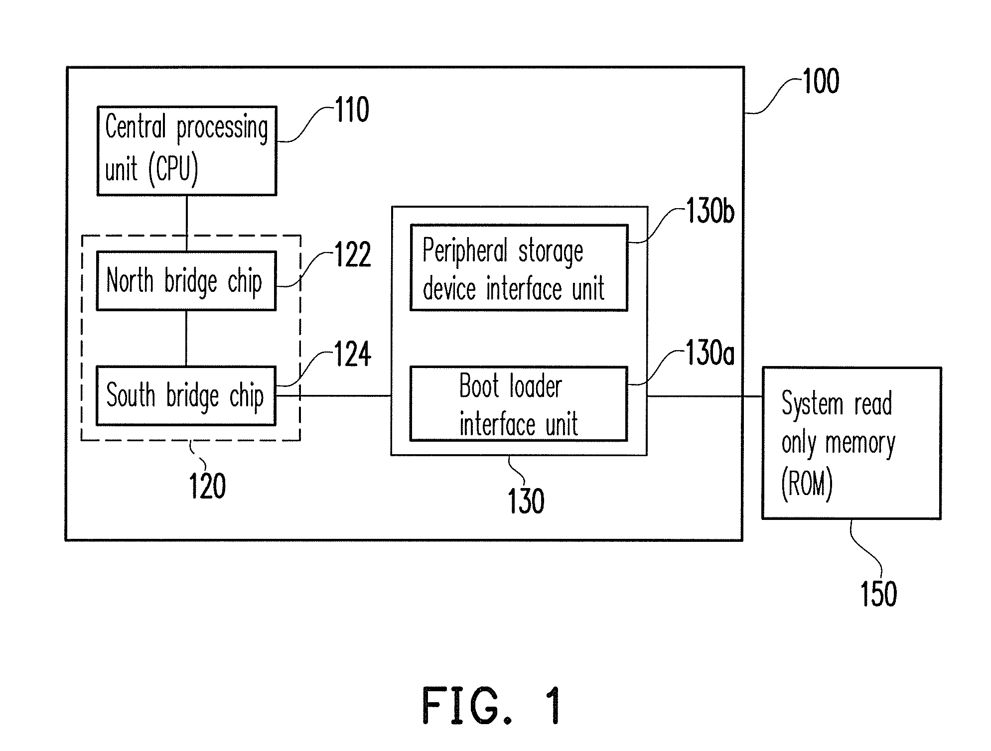
[0020]FIG. 1 is a schematic block diagram illustrating a motherboard system according to an exemplary embodiment of the present invention.

[0021]Referring to FIG. 1, the motherboard system 100 is disposed in a computer (not shown), and is used for connecting related components of the computer. The motherboard system 100 includes a CPU 110, a control unit 120 and an interface connector 130.

[0022]The CPU 110 interprets commands executed on the motherboard system 100 to control operations of the components connected to the motherboard system 100.

[0023]The control unit 120 is electrically connected to the CPU 110, and connects the CPU 110 to the other devices on the motherboard system 100...


PUM


Abstract

A motherboard system is provided. The motherboard system includes a central processing unit (CPU), a control unit and an interface connector. The control unit is electrically connected to the CPU. The interface connector is electrically connected to the control unit and has a boot loader interface unit and a peripheral storage device interface unit, wherein the boot loader interface unit is electrically connected to the control unit and is configured for electrically connecting a system read only memory. When the power of the motherboard system is turned on, the CPU sends a read only memory fetch cycle to the control unit and fetches a booting program from the system read only memory configured in an external device via the boot loader interface unit. Accordingly, the system read only memory can be conveniently updated and maintained.

Description

CROSS-REFERENCE TO RELATED APPLICATION[0001]This application claims the priority benefit of Taiwan application serial no. 97139530, filed on Oct. 15, 2008. The entirety of the above-mentioned patent application is hereby incorporated by reference herein and made a part of this specification.BACKGROUND[0002]1. Technology Field[0003]The present invention relates to a motherboard system. More particularly, the present invention relates to a motherboard system that can be booted via a removable system read only memory, a flash memory storage device having the system read only memory, and a connector for connecting the motherboard system and the flash memory storage device.[0004]2. Description of Related Art[0005]During booting of a personal computer (PC) system, a booting program (for example, a basic input / output system (BIOS)) initiates hardware devices of the PC, detects functions of the hardware devices and booting an operation system of the PC. Generally, the booting program is sto...

Claims


Application Information

Patent Timeline
Patent Type & Authority Applications(United States)
IPC IPC(8): G06F13/36
CPCG06F9/4406
Inventor CHO, YUNG-HSIANG
Owner PHISON ELECTRONICS
Learn More