Bidirectional solar tracker

a solar tracker and bi-directional technology, applied in the direction of solar heat collector controllers, solar heat collector mounting/support, moving/orienting solar heat collectors, etc., can solve the problems of energy production, inability to make exact aerodynamic calculations, simulation of turbulence, etc., to avoid unnecessary stress on the system, the critical speed for flutter increases appreciably

Inactive Publication Date: 2010-04-22
HISPANOTRACKER
View PDF7 Cites 43 Cited by
  • Summary
  • Abstract
  • Description
  • Claims
  • Application Information

AI Technical Summary

Benefits of technology

[0045]2.—Virtually total reduction in the phenomena of fluttering and resonance due to the effect of the wind on the system, since the kinetic energy acquired by the hydraulic oil in the form of heat is dissipated, avoiding unnecessary stresses on the system, such as the danger of entering into resonance which would destroy the facility or the actual solar tracker.
[0046]3.—Since the oleo-pneumatic damper is in movement, the critical speed for flutter increases appreciably.

Problems solved by technology

Although the systems referred to and based on the concept mentioned above are functionally efficient, they nevertheless present a series of drawbacks that can be summarized as follows:It is not possible to make any exact aerodynamic calculations, since the shapes of the tracker are not at all similar to standardized profiles, so the data that would be obtained from a test in a wind tunnel would differ from the conditions in the field, where it is impossible to simulate the turbulence owing to the undulations of each specific field.
In any case, the calculations are always orientative and so the emergency limit speed has to be reduced, with the consequent reduction in energy production.In those cases in which the direction of the wind is parallel to the solar panels, the system will move to the horizontal position even when this is not necessary, thus reducing the energy output.Even in the case of installing a wind gauge for each solar tracker, there exists a risk of vertical whirlwinds produced by thermal differences which, if they strike the surface of the tracker at one of its ends, might not be detected by the wind gauge, and a large torque or torsion would be produced due to a symmetric load which would cause serious damage to the solar tracker.

Method used


Image

  • Bidirectional solar tracker
  • Bidirectional solar tracker
  • Bidirectional solar tracker

Examples


Embodiment Construction

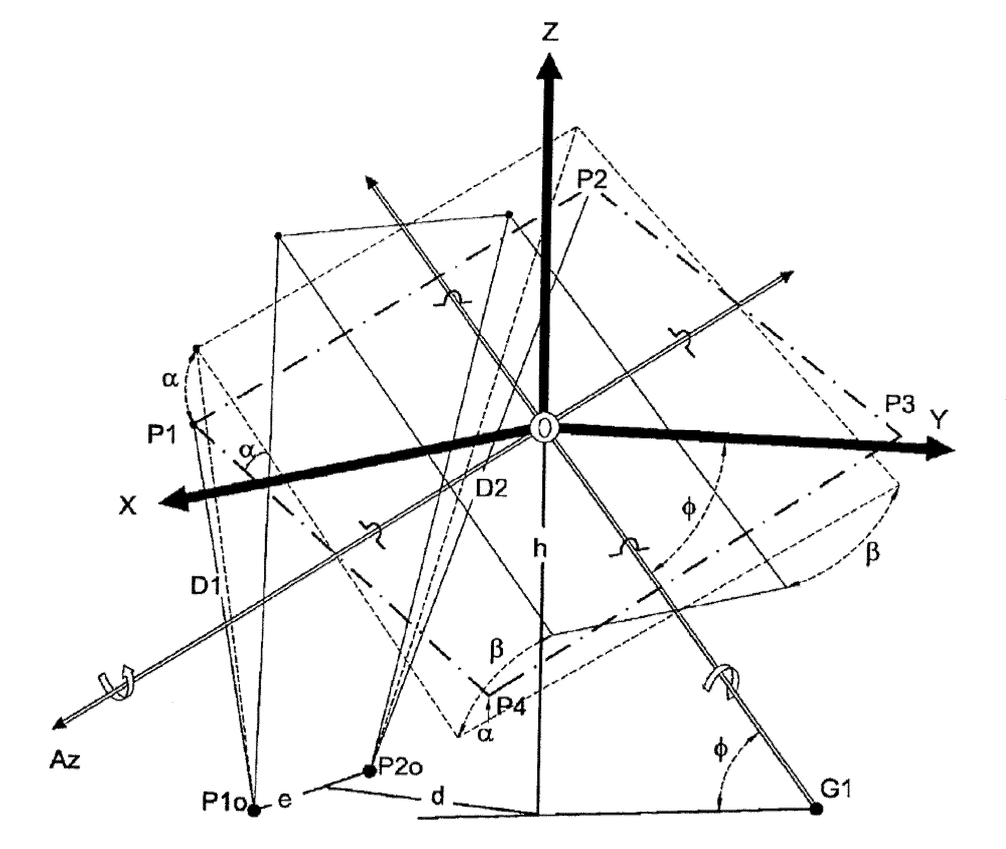
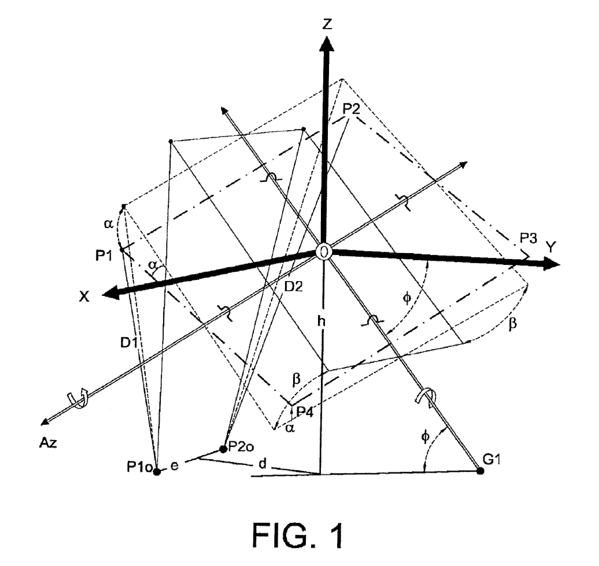
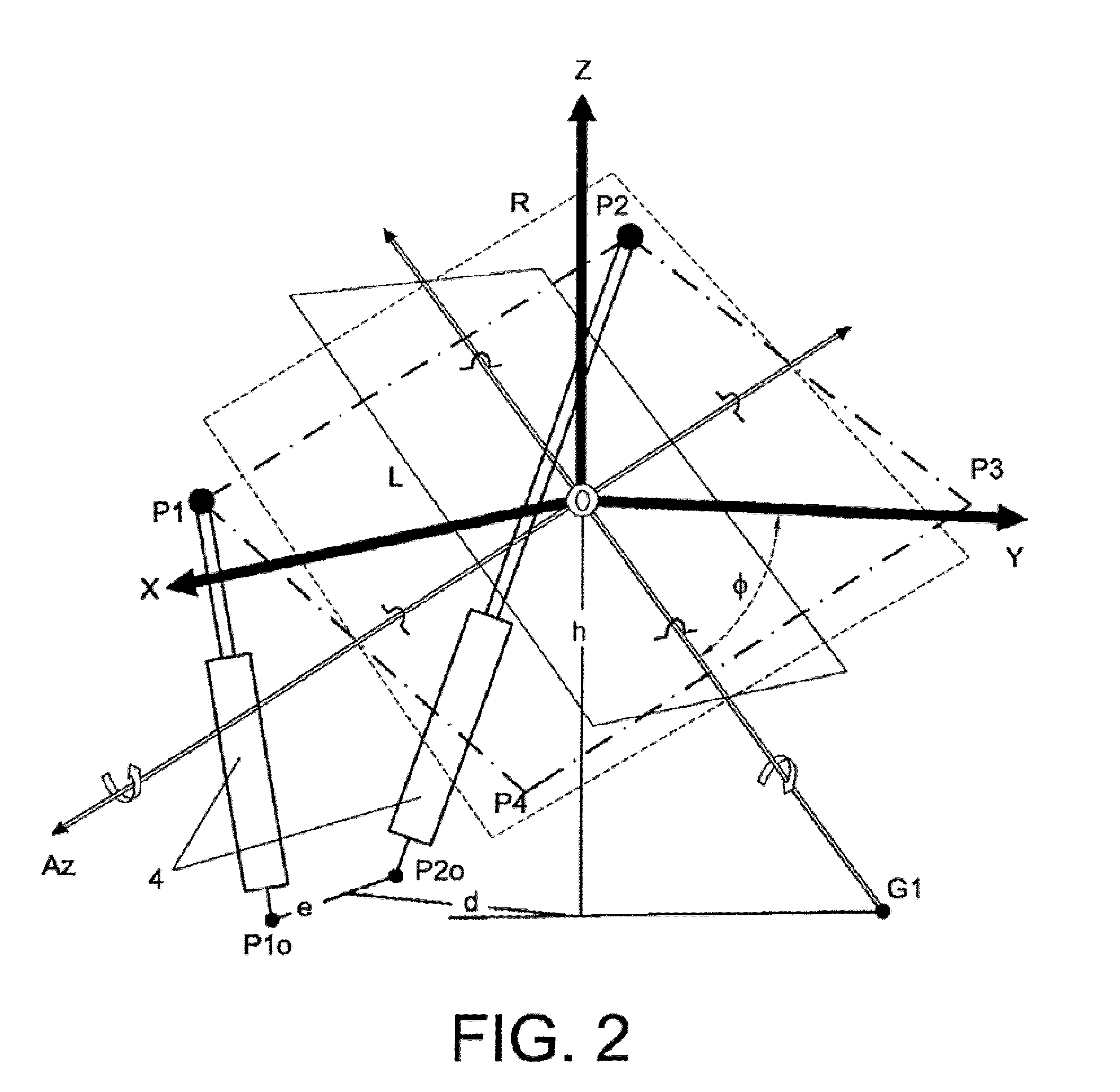
[0021]In general terms, the bidirectional solar tracker proposed by the invention achieves the orientation of the platform carrying the solar panels by being arranged on a support structure, in such a way that it can rotate and orientate itself with combined movements of rotation about two axes: one of them oblique and fixed to the ground forming a certain angle with the OY coordinate axis parallel to the surface of the ground and which points in the southerly direction; and the other axis perpendicular to the previous one, contained in the plane of the platform and which varies its angle of inclination when the platform varies its angle about the fixed oblique axis.

[0022]This movement is carried out with two actuators respectively connected to separate fixed points of the ground and to the same number of vertices of the platform, causing the latter to rotate about a central support point thereof in the support structure and from an initial position to another final position, having...


PUM


Abstract

The tracker is formed by a structure (3) bearing a platform (1) carrying the solar panels (2) that varies both the azimuth and elevation orientation thereof in order to track the sun. This movement is achieved by means of two actuators (4) connected respectively to fixed points (P1o, P2o) on the ground and other vertices (P1, P2) of the platform (1), thereby causing the platform to rotate around a central support point “O” of the same. The distances (D1, D2) between the points which join the actuators (4) have a one-to-one relation with the rotation angles (β, α) of the platform (1) around both perpendicular axes: an oblique fixed axis (O-Cl) and another axis (0-Az) that angularly varies the inclination thereof with respect to the first.

Description

OBJECT OF THE INVENTION[0001]The present invention relates to a bidirectional solar tracker which contributes notable relevant characteristics and technical advantages with regard to those currently existing for the production of electrical energy by means of solar panels.[0002]The main object of the invention is to offer a support structure for a platform carrying the solar panels, such that this platform is orientated towards the sun according to a novel form of movement, with a functioning that is smooth and simple, yet efficient.[0003]In the current field of exploiting renewable energies, there exists a great increase at the world level in solar energy facilities that use photovoltaic panels (solar panels), which convert that energy into electrical energy. The installation of these panels is normally done on fixed structures orientated is towards the south, with a degree of inclination on the horizon that depends on the latitude of the place.[0004]The production of electrical en...

Claims


Application Information

Patent Timeline
Patent Type & Authority Applications(United States)
IPC IPC(8): F24J2/40F24J2/38F24S50/20
CPCF24J2/523Y02E10/47F24J2002/5441F24J2/5424F24S30/455F24S2030/115F24S25/10
Inventor CARRASCO MARTINEZ, CARLOS MARIA
Owner HISPANOTRACKER
Why Eureka
Try Eureka