Overpressure absorption mechanism for fluid bed processors

Active Publication Date: 2015-01-08
FREUND VECTOR
View PDF3 Cites 0 Cited by
  • Summary
  • Abstract
  • Description
  • Claims
  • Application Information

AI Technical Summary

Benefits of technology

[0010]A fluid bed processor is constructed with a movement mechanism which functions during an internal explosion to minimize damage to the processor by allowing clamp rings to engage and contain the forces within the container. The processor has upper and lower housing sections which are normally joined, yet separable from one another for loading and unloading the processor, and for cleaning and maintenance purposes. The lower housing is mounted on legs, each

Problems solved by technology

With some particles, there is a risk of explosion during the processing, creating an overpressure which must be contained within the container.
The clamp rings allow the hous

Method used


Image

  • Overpressure absorption mechanism for fluid bed processors
  • Overpressure absorption mechanism for fluid bed processors
  • Overpressure absorption mechanism for fluid bed processors

Examples


Embodiment Construction

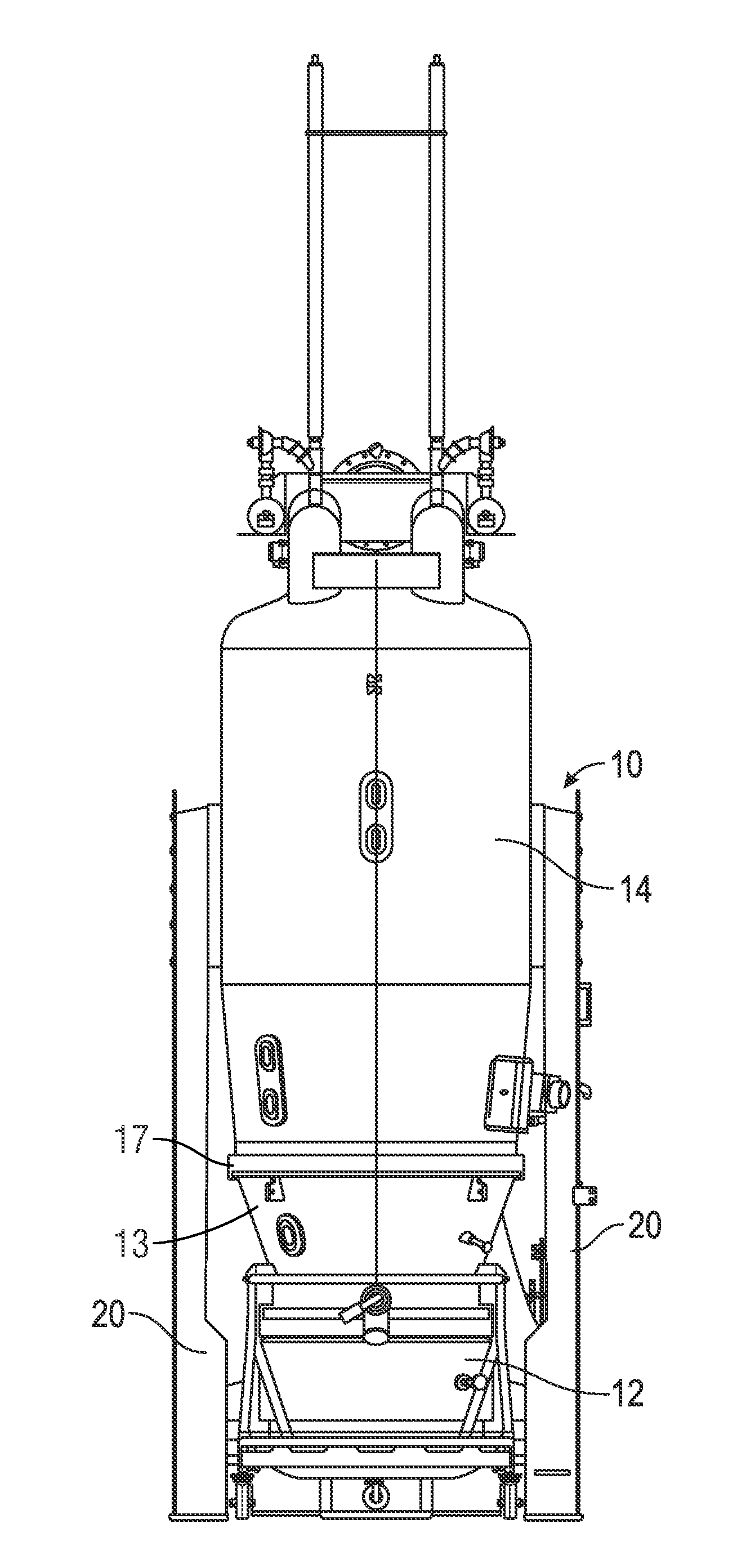
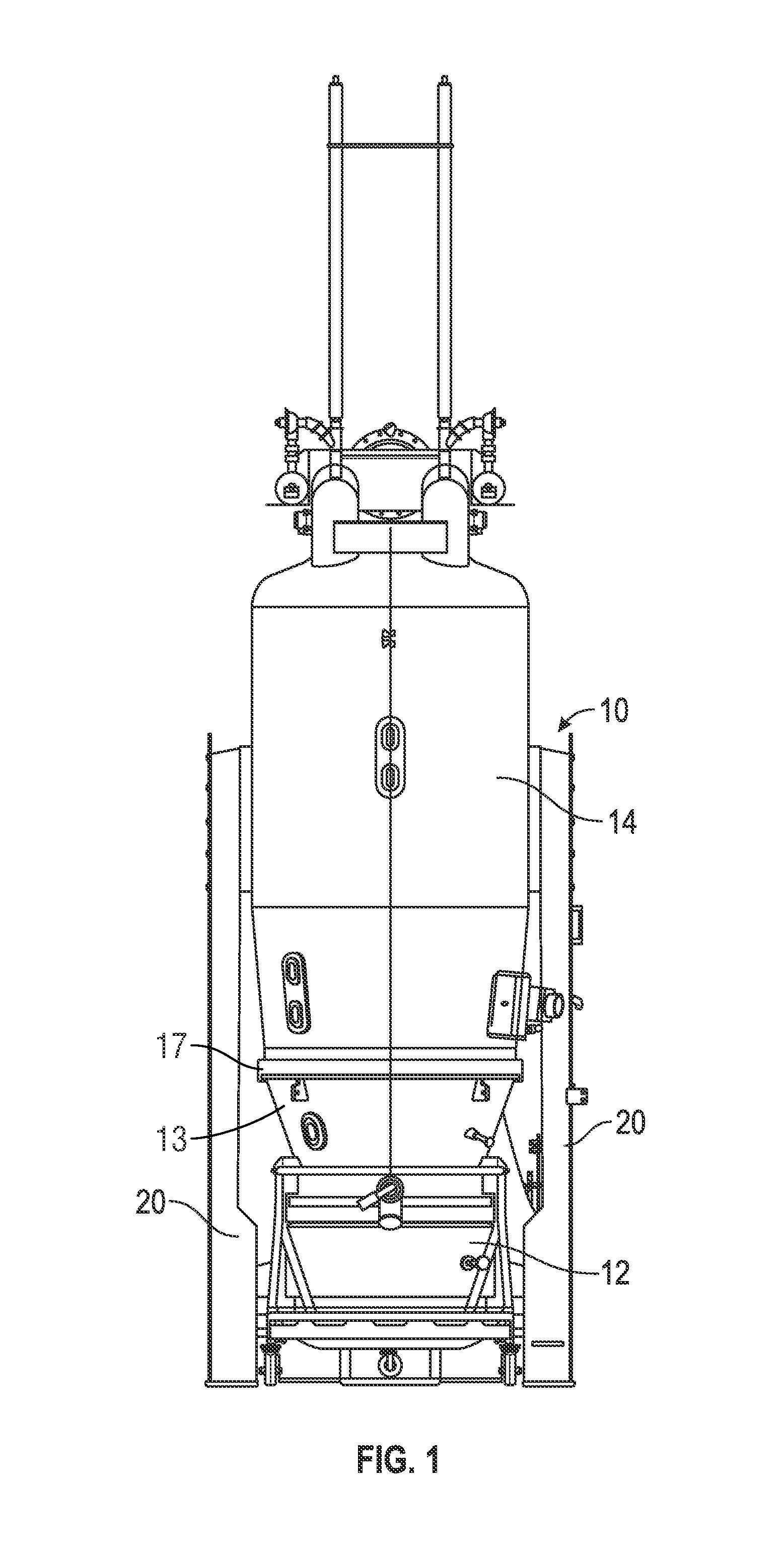
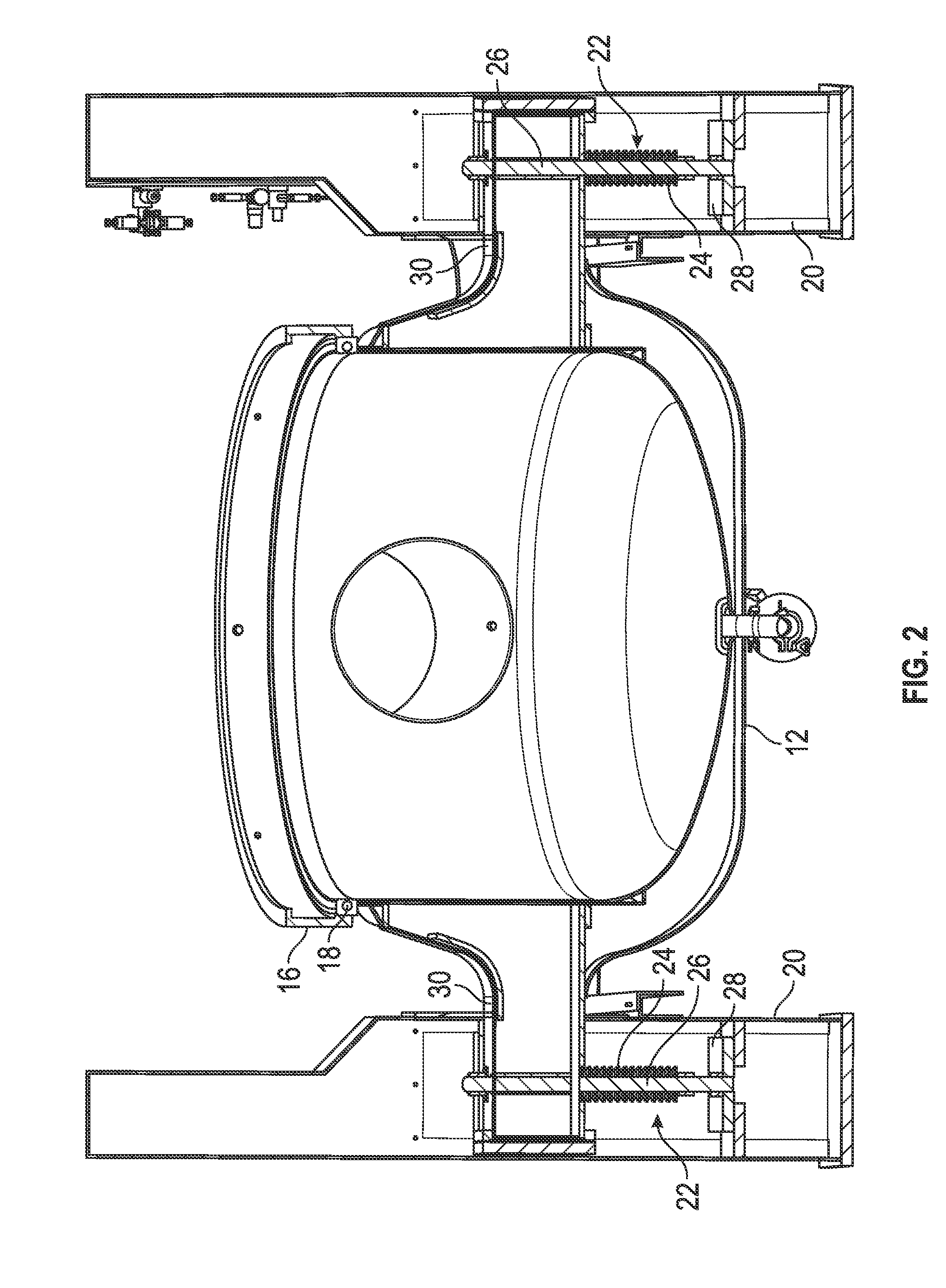
[0016]A fluid bed processor is generally designated by the reference numeral 10 in FIG. 1. The processor 10 includes a lower housing section 12, a product containing section 13 and an upper housing section 14, which are joint or coupled together to form the container for the processing chamber and expansion chamber of the processor 10. A ring 16 extends around the juncture of the lower and middle housings 12, 13, with a seal 18 extending along the perimeter edge of the lower housing 12, as best seen in FIG. 2. A similar ring 17 and seal arrangement is formed along with the perimeter edge of the middle and upper housings 13, 14. The lower housing 12 and upper housing 14 are supported by a plurality of legs 20.

[0017]The present invention is directed towards a movement mechanism 22 for the processor 10. The movement mechanism 22 is an energy absorbing assembly comprised of spring(s) 24, with one spring assembly mounted in each of the legs 20. The springs are shown to be Belleville wash...


PUM


Abstract

An overpressure absorption mechanism is provided for a fluid bed processor. The mechanism includes spring assemblies mounted in the legs of the processor. The arms of the lower housing section extend into the legs and are supported on the springs. If an overpressure condition arises within the processor, the springs compress to allow movement between the housing sections to allow engagement of clamping rings which contain the over pressure condition.

Description

BACKGROUND OF THE INVENTION[0001]Fluid bed processors are used for coating, granulating, and drying various types of particles, such as pharmaceuticals, powders, seeds, pellets, and the like. The processor has sections which can be separated for loading and unloading particles and for cleaning, with the sections being sealed together during processing. With some particles, there is a risk of explosion during the processing, creating an overpressure which must be contained within the container. For example, some conventional fluid bed processors have a 12 bar construction and utilize clamp rings at the joints or separation points between the housing sections, so as to be able to withstand an internal pressure of 12 bars. By design, there is clearance between the clamp rings and their associated seal rings to allow for separation of the container sections. The clamp rings allow the housing sections to contain the pressure and separation forces within the container itself during a 12 b...

Claims


Application Information

Patent Timeline
IPC IPC(8): F16L55/05F17D5/00
CPCF17D5/00F16L55/05B01J8/1809B01J8/1872B01J2/16Y10T137/0396
Inventor CLARK, JAMES ALANWRIGHT, NIGEL P.BASTEN, AARON K.
Owner FREUND VECTOR
Why Eureka
Try Eureka