
Novel assembly type rotary energy dissipation pier anti-collision device

An anti-collision device and assembled technology, which is applied in the direction of road safety devices, bridges, bridge parts, etc., can solve the problems of complex construction process, long construction period, heavy structure, etc., and achieve the effect of shortening the construction period and convenient and fast construction

Pending Publication Date: 2021-09-17
HUAQIAO UNIVERSITY
View PDF0 Cites 0 Cited by
  • Summary
  • Abstract
  • Description
  • Claims
  • Application Information

AI Technical Summary

Problems solved by technology

However, these anti-collision measures mainly have the following four defects: (1) The direct pouring of the cap at the bottom of the bridge will affect the mechanical performance of the bridge and cannot be replaced in time when the reinforced concrete anti-collision platform on the outside of the bridge pier is damaged by impact; (2) Whether it is pouring reinforced concrete on the outside of the pier or setting up a complex anti-collision mechanism, the construction process is complicated and the construction period is long, which is not conducive to the rapid recovery of urban traffic; (3) such devices that use rotation to consume energy and change vehicle tracks are often due to structural Bulky and ill-conceived internals make it difficult for the device to actually spin in the event of a vehicle impact, so the device does not perform as intended
(4) A truly rotatable anti-collision device may change the running track of the vehicle during the rotation process, which will bring safety hazards to people and vehicles in adjacent lanes

Method used


Image

  • Novel assembly type rotary energy dissipation pier anti-collision device
  • Novel assembly type rotary energy dissipation pier anti-collision device
  • Novel assembly type rotary energy dissipation pier anti-collision device

Examples


Embodiment Construction

[0032] The following will clearly and completely describe the technical solutions in the embodiments of the present invention with reference to the accompanying drawings in the embodiments of the present invention. Obviously, the described embodiments are only some, not all, embodiments of the present invention. Based on the embodiments of the present invention, all other embodiments obtained by persons of ordinary skill in the art without making creative efforts belong to the protection scope of the present invention.

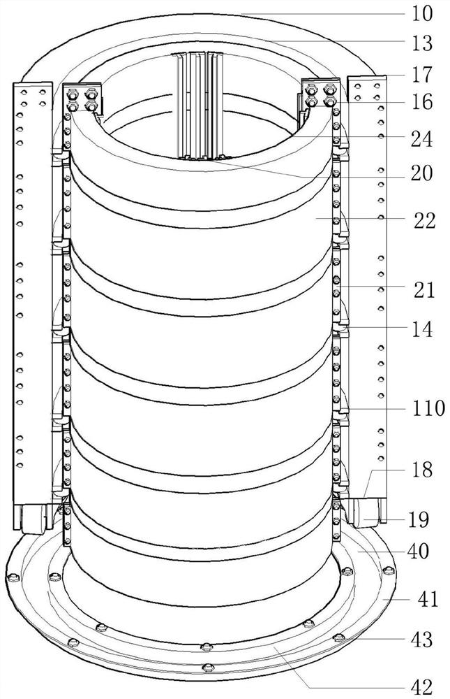
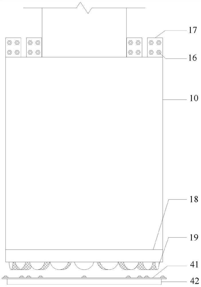
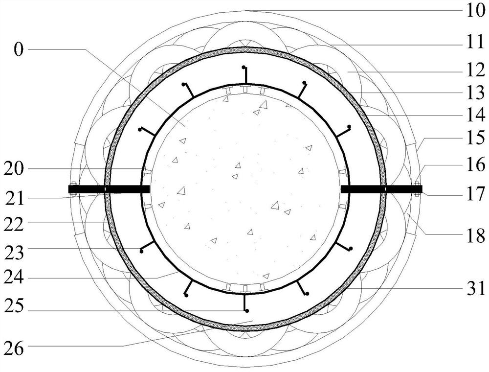
[0033] The purpose of the present invention is to provide a novel assembly-type anti-collision device for rotating energy-dissipating bridge piers to solve the above-mentioned problems in the prior art, which can effectively dissipate the kinetic energy of the vehicle and make the vehicle stop after turning a certain angle Avoid potential safety hazards; and the anti-collision device also has the characteristics of convenient and quick on-site construction, whi...


PUM


Abstract

The invention discloses a novel assembly type rotating energy dissipation bridge pier anti-collision device. A main body structure comprises a rotating layer surrounding the outer side of a bridge pier, a rigid layer, a rotation limiting connecting mechanism and a bottom rail bottom plate. Vertical and transverse pulleys are installed at the bottom and on the side face of the rotating layer correspondingly and matched with the bottom rail bottom plate to rotate around the rigid layer within the limiting range of the limiting rotating connecting device. Low-yield-point steel and high-strength steel are cooperatively used externally to form a thin film effect for deformation energy dissipation, the waste tires and the rigid layer are utilized internally to directly resist impact, and vehicle kinetic energy is fully consumed through rotation of the rotating layer and the rotation limiting mechanism. Effective deformation and rotation energy consumption can be achieved, and the assembly type energy dissipation device is of an assembly type structure and can be rapidly installed and replaced.

Description

technical field [0001] The invention relates to the technical field of bridge pier protection in bridge engineering, in particular to a novel assembled rotating energy-consuming bridge pier anti-collision device. Background technique [0002] In the process of modernization, bridges, as buildings spanning special geographical environments and providing space for other traffic, are widely used in urban road construction in our country. With the improvement of people's quality of life, cars have increasingly become the means of transportation for most people to travel, which has also led to the continuous increase in the number of cars in our country. As land traffic becomes more and more busy, in order to relieve traffic pressure, bridges have been widely used. Bridges can effectively relieve urban traffic pressure and improve urban operating efficiency. It has become an indispensable part of social life. Just because of the continuous increase of the number of cars and the...

Claims


Application Information

Patent Timeline
Patent Type & Authority Applications(China)
IPC IPC(8): E01D19/02E01F15/14
CPCE01D19/02E01F15/141
Inventor 江凯萍李海锋杨钦聪
Owner HUAQIAO UNIVERSITY
Learn More