Multiple concentric cylindrical co-coiled heat exchanger

a heat exchanger and concentric helical coil technology, applied in the direction of indirect heat exchangers, heat exchange apparatus, lighting and heating apparatus, etc., can solve the problems of multiple co-coiled concentric helical coils that have multiple concentric helical coils, serious flow imbalance, and difficulty in re-circuiting, etc., to achieve low tube count, high flow resistance, and low tube count

Inactive Publication Date: 2010-04-22
ERICKSON DONALD CHARLES
View PDF37 Cites 57 Cited by
  • Summary
  • Abstract
  • Description
  • Claims
  • Application Information

AI Technical Summary

Problems solved by technology

This has been found to cause a serious flow imbalance.
The tube gaps could be increased for the shorter inner tubes, thus increasing shell flow across those tubes, but that would not solve the problem, as the tubes would get even shorter, so there would be even less transfer area and larger tube side flow.
Note however that this requires complicated re-circuiting in the middle of the bundle(s) of coils.
However the prior art shell and coil exchangers with multiple co-coiled concentric helical coils encounter a problem when striving for compactness.
In summary, with prior art multiple co-coiled in-line configurations, the gaps cannot be made very small, and hence the bundle cannot be very compact.
Unfortunately the counter-coiled configuration does not satisfy all heat exchange requirements.
In particular, there are heat exchange applications wherein there is a great disparity between the flow area required on one side of the exchanger versus that on the other.
Since there is much higher flow resistance at the in-line regions compared to the staggered regions, and the various in-line regions can randomly accumulate more in some areas than in others, serious flow maldistribution can result on the shell side.

Method used


Image

  • Multiple concentric cylindrical co-coiled heat exchanger
  • Multiple concentric cylindrical co-coiled heat exchanger
  • Multiple concentric cylindrical co-coiled heat exchanger

Examples


Embodiment Construction

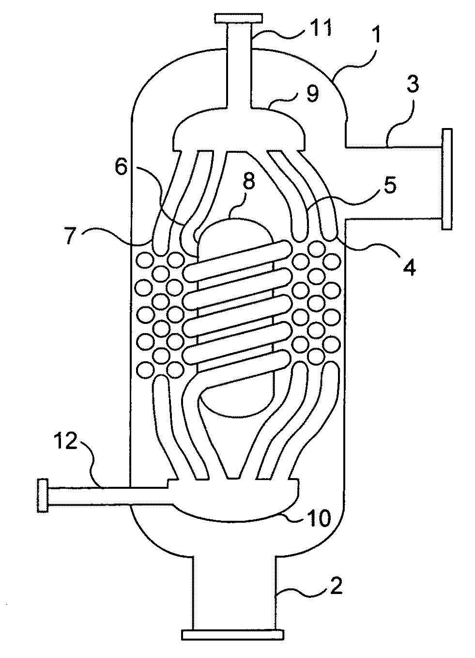
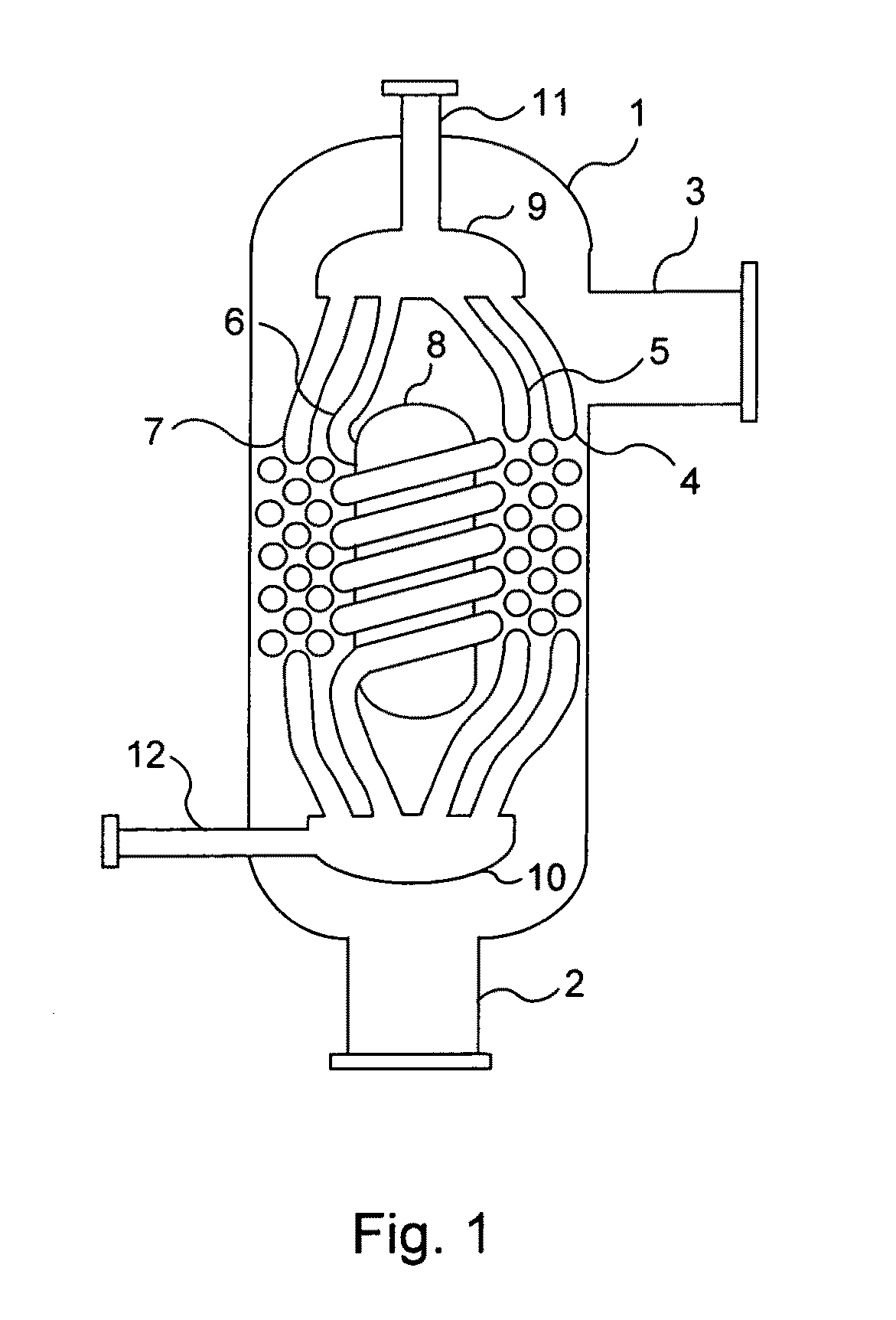
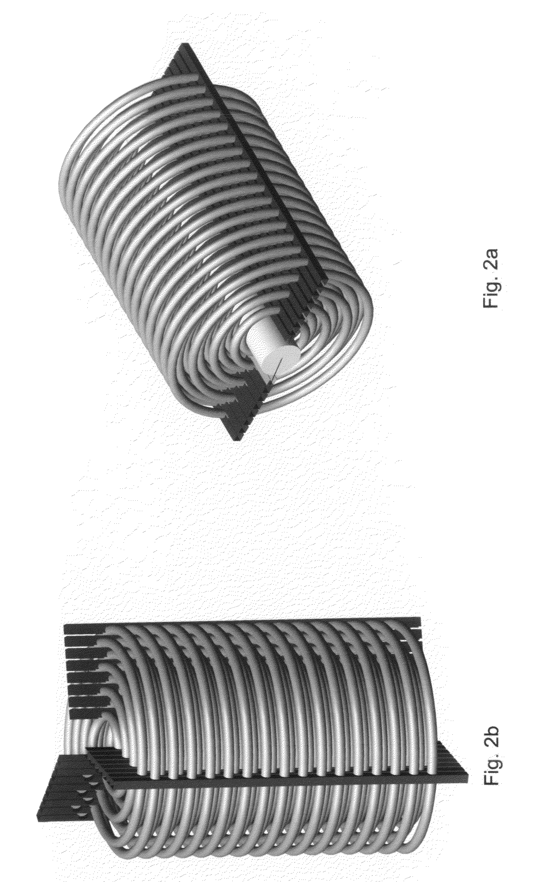
[0020]FIG. 1 illustrates the basic overall heat exchanger configuration disclosed: cylindrical shell 1 with shell-side inlet 2 and outlet 3; multiple co-coiled concentric helical coils of tubing 4, 5, 6, and 7; core blocker 8; tube headers 9 and 10 for the tubes at each end of the bundle of tube coils; and the tube header connectors 11 and 12. The critical features that enable the compactness are the close proximity or spacing of adjacent tubes, plus their staggered alignment. That close spacing and alignment is established and maintained by spacers, which are shown in subsequent figures. The illustrated shell-side upflow arrangement is the preferred configuration when it is used as a refrigerant heat exchanger.

[0021]Whereas FIG. 1 illustrates gathering all the tubes at each end of the bundle to a single tubesheet and header, the artisan will recognize that it is possible to divide the tubes into two or more groups, and provide a separate pair of tubesheets and headers for each grou...


PUM


Abstract

A compact shell and coil heat exchanger is disclosed that accommodates widely differing volumetric flowrates between the two fluids undergoing heat exchange. Multiple co-coiled helical coils of tubing are concentrically arranged, and coil spacers are provided which maintain the tubes in overall staggered alignment, as illustrated in FIG. 1. Uniformly high transfer coefficients are maintained throughout the bundle of coils via means for ensuring that the tube-side flow through the tubes of each coil, and the shell-side flow across each coil, are kept proportional to the tube surface area of each coil.

Description

CROSS REFERENCE TO RELATED APPLICATIONS[0001]Not ApplicableSTATEMENT REGARDING FEDERALLY SPONSORED RESEARCH AND DEVELOPMENT[0002]Not ApplicableBACKGROUND OF THE INVENTION[0003]Shell and coil heat exchangers have found wide-ranging use in commerce and industry. Whereas various shell geometries and coil geometries are found in the prior art, the ones of interest here are cylindrical shells which contain helically coiled tubing, where the tube coils are also cylindrical in shape. One prior art example of a single cylindrical coil contained in a cylindrical shell is found in U.S. Pat. No. 6,044,837. Note the central core flow blocker, which forces all shell-side flow through the helical coil region. Note also the wide gap between adjacent loops of the tube coil (the “tube gap”). That gap provides the flow space for the shell side fluid, which follows a helical path countercurrent to the tube fluid flowpath.[0004]Of particular interest for this disclosure are the cylindrical shell helica...

Claims


Application Information

Patent Timeline
Patent Type & Authority Applications(United States)
IPC IPC(8): F28D7/12F28D7/02
CPCF28D7/024F28F2240/00F28F9/0132
Inventor ERICKSON, DONALD CHARLES
Owner ERICKSON DONALD CHARLES
Why Eureka
Try Eureka