Gripper mechanism with two driveshafts per gripping finger

a technology of gripper and drive shaft, which is applied in the direction of manipulators, load-engaging elements, programme-controlled manipulators, etc., can solve the problems of difficult configuration of gripping jaws, limited gripping fingers, and inability to completely swing the gripping fingers sideways,

Active Publication Date: 2010-04-22
SAADAT M MOHSEN
View PDF7 Cites 10 Cited by
  • Summary
  • Abstract
  • Description
  • Claims
  • Application Information

AI Technical Summary

Benefits of technology

[0006]Against this background, the invention has as an object to create a gripper mechanism, the gripping finger of which can swing away completely from the operating region ahead of the gripper body, in any gripping position, i.e. even in the final and extended position, safely and without tipping over, in order to combine the broadest possible application of angular and parallel grippers with one another.
[0009]As a result of the guidance of the gripping finger by two drive shafts, which, in turn, are each driven by a crank, a chain, a gear wheel, a flat belt, a toothed driving belt or a connecting bar, it is possible to move the gripping finger beyond its final or extended position of its guide mechanism, even beyond 180° pivoting of the drive shaft and in doing so safely to transmit forces and torque without tilting over or entering into an unstable position.
[0014]Coaxially about the neck bearings, below the connecting bars driven by the drive shafts, axial sealing rings are advantageously placed, which hermetically seal the gripper casing in order to prevent the influx of dust and dirt into the gripper casing.
[0020]The bending moment and torque act in each of the connecting bars as a tensile or compressive load, whereby the loadability of the gripper is increased enormously. For dusty environments and for explosion-protected applications flat axial seals are employed at the end of the neck bearings outside of the bearing surfaces, but below the driven connecting bars or below the head of the end support bearing in order to seal the gripper mechanism completely.
[0025]A thus designed gripper mechanism guides each of its gripping fingers by way of two driven connecting bars or connecting bar pairs serving as a coupler of a multi-member articulated linkage system, even beyond the extended and final positions of its drive members reliably and unambiguously onwards without tilting over or jamming. In this manner, it becomes possible to provide a different range of movement even beyond 180° for each gripping finger and to swing it away out of the operating region ahead of the gripper even when the movement is parallel and to keep the space ahead of the gripper casing available for other tasks.

Problems solved by technology

However, they suffer from the great disadvantage that they apply their gripping fingers for different sizes of objects at differing angles against the object which renders the configuring of the gripping jaws as well as the use of the gripper for objects of different sizes to be gripped difficult and greatly limited.
The parallel grippers, which conduct their gripping fingers as connecting rods of a linkage parallelogram on the other hand suffer from the disadvantage that their gripping fingers cannot be completely swung sideways out of the operating region ahead of the gripper casing, because the linkage parallelogram assumes an unstable position, the final or extended position, in which the gripping finger cannot apply force to the object being gripped and may in this position also continue to run in anti-parallel fashion.

Method used


Image

  • Gripper mechanism with two driveshafts per gripping finger
  • Gripper mechanism with two driveshafts per gripping finger
  • Gripper mechanism with two driveshafts per gripping finger

Examples


Embodiment Construction

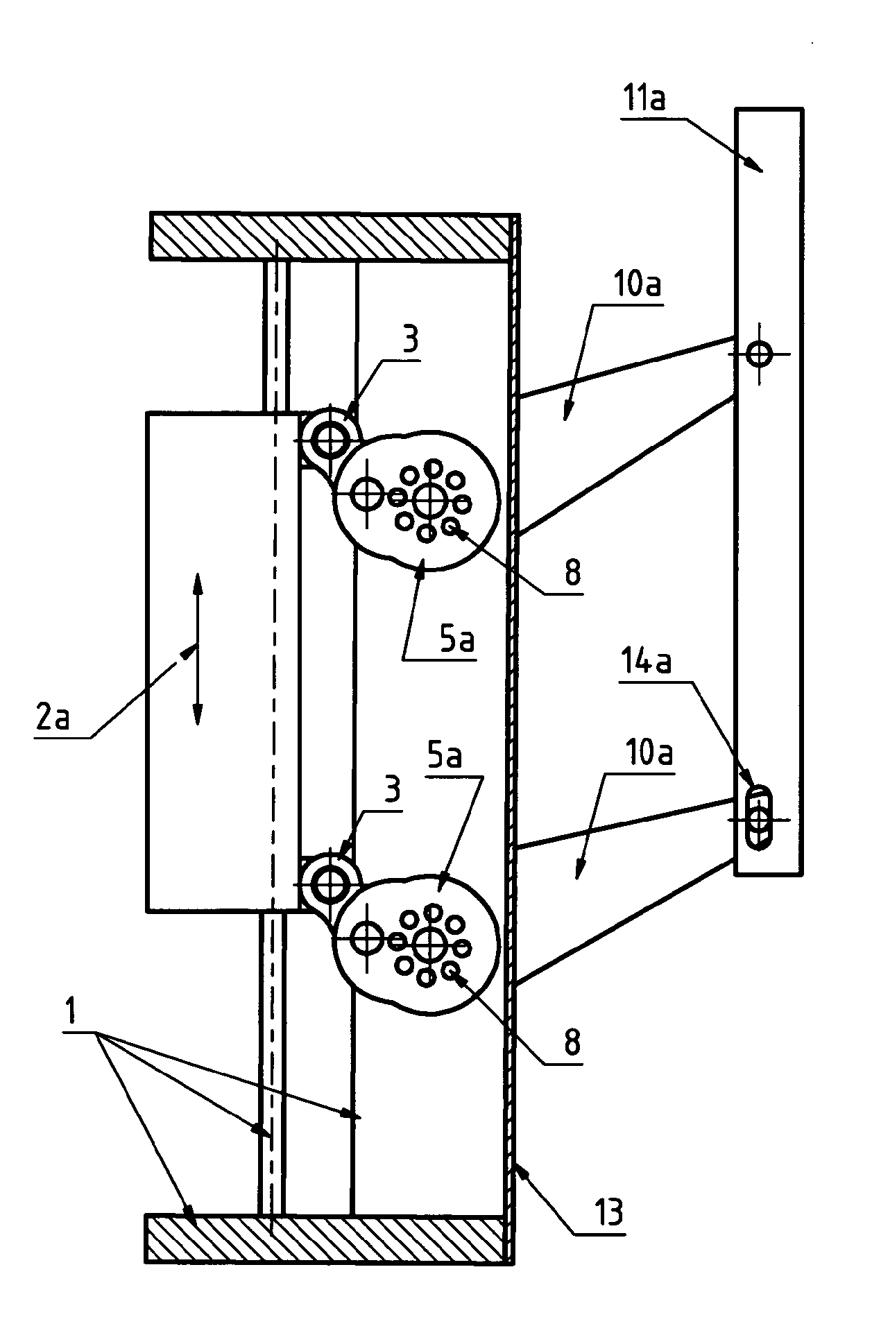
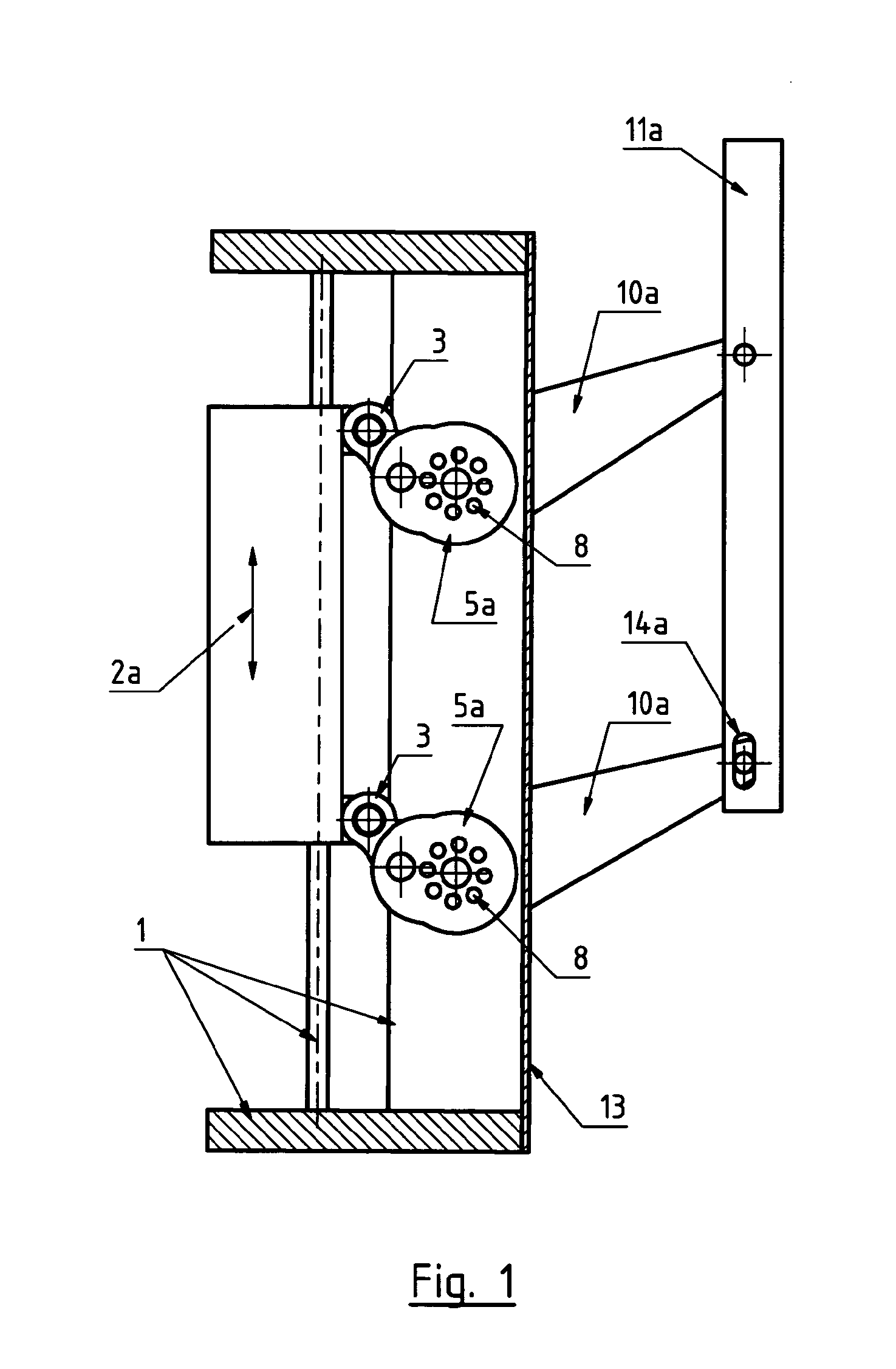
[0032]According to FIG. 1 the gripper mechanism comprises a stable gripper casing (1), which is to be fitted to the flange of the robot. Within the gripper casing (1) an actuating unit, not illustrated, is accommodated, which pneumatically, hydraulically or electro-motorically brings about translatory movement of the slider (2a). The slider (2a), by means of the couplers (3), drives the crank shafts (5a), which are preferably of multi-section design, and which are fitted to the connecting bars (10a) in positive, yet separable engagement. The connecting bars (10a) at their ends guide the gripping finger (11a) in articulated relationship. Whereas the uppermost connecting bar (10a) is connected to the gripping finger (11a) by a pivoting journal, the lower connecting bar (10a) guides another point of the gripping finger (11a) in a sliding linkage (14a). This permits the connecting bars (10a) to be of different length or the crank shafts (5a) to revolve by different angles, in order to p...


PUM


Abstract

The invention relates to a gripper mechanism for machines, robots and manipulation devices, comprising at least one moving gripping finger, operated by coupling to an operating mechanism by two drive shafts. As a result of operating the gripping finger by two connecting bars, in turn each driven by the drive shafts, it is possible to move the gripping finger through a rotation over 180° through the path or range thereof and hence securely transmit forces and torques without tipping or getting in an unstable position. According to the invention, the drive shafts are divided axially into at least two parts in order to be housed completely in an enclosed and unitary gripper housing, protected from dust and dirt and hermetically sealed. The different parts of the drive shafts are centered on one another and positively connected by means of axial toothing, in the form of pinion gears and pins, and have a carrier support bearing.

Description

CROSS-REFERENCE TO RELATED APPLICATION[0001]This application is an U.S. national phase application under 35 U.S.C. §371 based upon co-pending International Application No. PCT / DE / 2008 / 001364 filed on Aug. 19, 2008. Additionally, this U.S. national phase application claims the benefit of priority of co-pending International Application No. PCT / DE / 2008 / 001364 filed on Aug. 19, 2008 and German Application No. 10 2007 039 398.0 filed on Aug. 21, 2007. The entire disclosures of the prior applications are incorporated herein by reference. The international application was published on Feb. 26, 2009 under Publication No. WO 2009 / 024137.BACKGROUND OF THE INVENTION[0002]1. Field of the Invention[0003]The invention relates to a gripper mechanism for machines, robots and handling equipment, comprising at least one movable gripping finger, which, serving as a coupling member of a guiding transmission, is driven by two drive shafts, a crank shaft, belt pulley 5 shaft or pinion or gear wheel or c...

Claims


Application Information

Patent Timeline
Patent Type & Authority Applications(United States)
IPC IPC(8): B25J15/00B25J15/02B25J15/08
CPCB25J9/1035B25J9/104B25J9/105B25J15/106B25J9/109B25J15/0266B25J15/08B25J9/1065
Inventor SAADAT, MOHSEN
Owner SAADAT M MOHSEN
Why Eureka
Try Eureka