
Network video surveillance system and recorder

a video surveillance system and network video technology, applied in the field of network video surveillance system recorders, can solve the problems of preventing full access to high-quality images for clients, requiring certain limitations on some users' access to surveillance images, and difficult integration with controls

Inactive Publication Date: 2010-04-22
IONICS INC
View PDF7 Cites 25 Cited by
  • Summary
  • Abstract
  • Description
  • Claims
  • Application Information

AI Technical Summary

Benefits of technology

[0009]Bearing in mind the problems and deficiencies of the prior art, it is therefore an object of the present invention to provide an improved video surveillance system and method that is able to create and manage multiple video streams at different compression types and different video quality parameters.
[0010]It is another object of the present invention to provide a video surveillance system and method of controlling a video surveillance system that permits clients to access simultaneously different levels of video quality for different users, for both live and recorded images.
[0011]It is a further object of the present invention to provide a video surveillance system and method of controlling a video surveillance system that permits multiple client users to access simultaneously and independently both live and recorded images in numbers and at video quality levels beyond those created by the video camera output.

Problems solved by technology

Even where high quality, high bandwidth video surveillance cameras are employed, other limitations prevent full accessibility of high quality images to clients.
Additionally, a client may require certain limitations on some of its users' access to the surveillance images.
Typical video surveillance systems are stand alone systems that are difficult to integrate with controls and do not provide to client users visibility to events in the entire system.

Method used


Image

  • Network video surveillance system and recorder
  • Network video surveillance system and recorder

Examples


Embodiment Construction

)

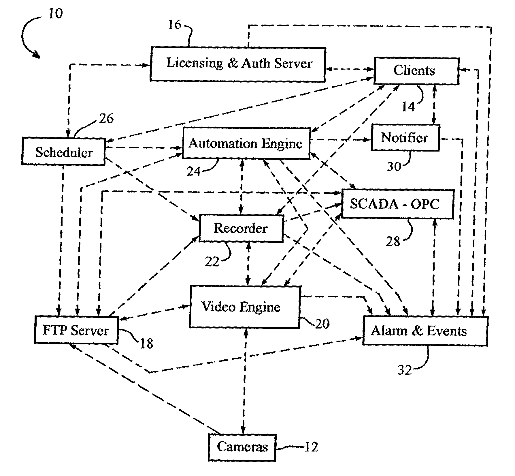
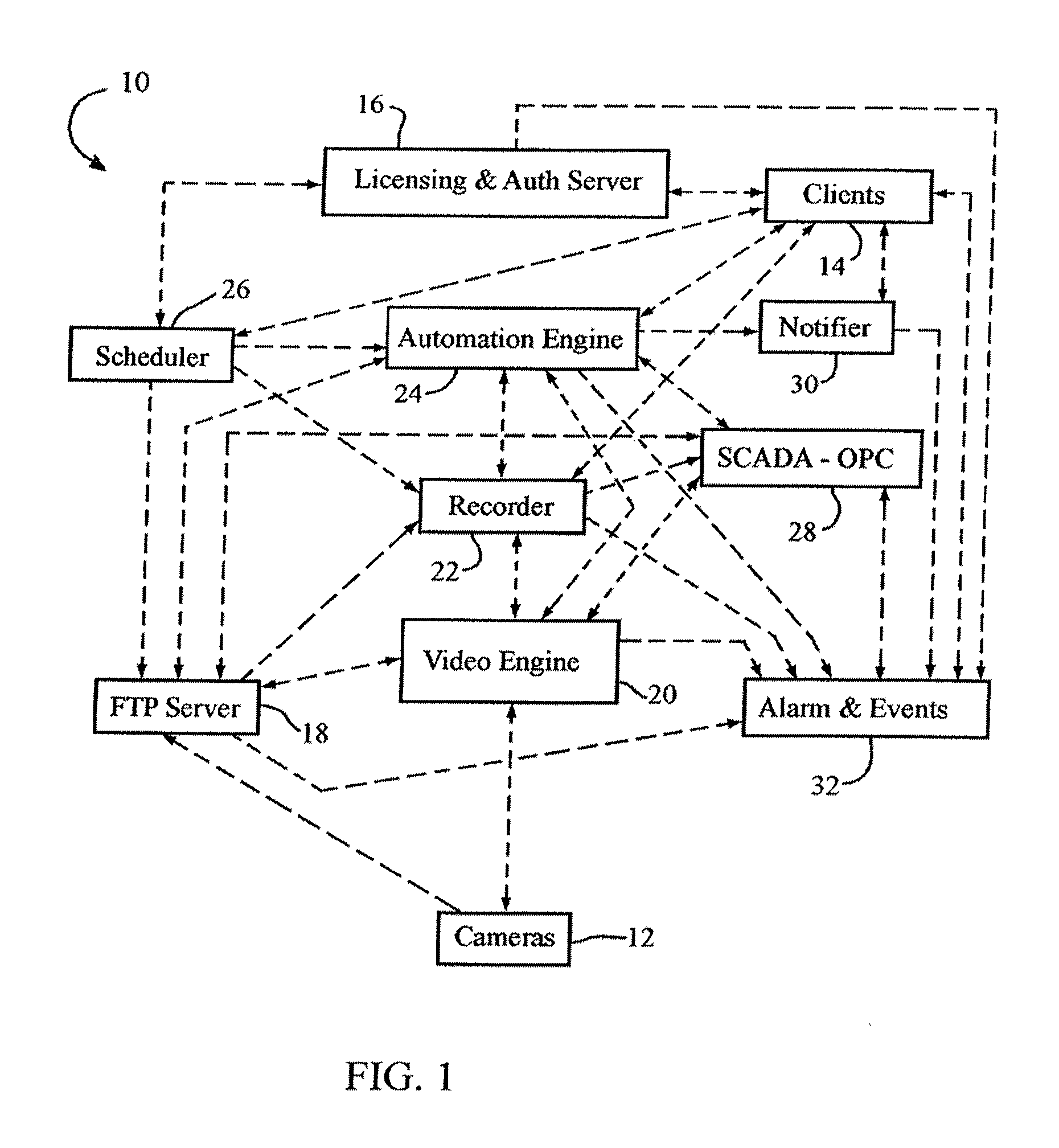
[0033]In describing the preferred embodiment of the present invention, reference will be made herein to FIG. 1 of the drawings in which like numerals refer to like features of the invention.

[0034]The present invention provides a Network Video Recorder (NVR) system that manages and controls many surveillance cameras with multiple users. The NVR system records multiple cameras simultaneously while managing concurrent users giving them access to real-time and archived video from anywhere on their internal network (LAN), across their wide area network (WAN) and / or over the Internet.

[0035]As shown in FIG. 1, the preferred Network Video Recorder (NVR) system 10 of the present invention consists of a number of functional controllers, servers, components or modules (also referred to as “engines”) that may be stand-alone and individually programmed or may be integrated into a general or special purpose computer system. The modules include Licensing and Authentication Server 16, Fast Transfe...


PUM


Abstract

A video surveillance method and system controls and distributes video signals from multiple surveillance cameras to multiple video clients by receiving a single original video signal stream from a camera and simultaneously converting it a plurality of video streams, with each video stream having a different video quality parameter. The different quality parameters may be different resolutions, degrees of compression, different frame rates, presence or absence of colors, intensity of colors, different contrast levels and different brightness levels. The video clients are entitled to access specified video quality parameters, and are simultaneously sent the converted video streams with the different video quality parameter to which they are entitled to access.

Description

BACKGROUND OF THE INVENTION[0001]1. Field of the Invention[0002]This invention relates to a video surveillance system recorder, and a method of controlling and distributing live or recorded video signals from video surveillance cameras to multiple video clients.[0003]2. Description of Related Art[0004]Typical surveillance cameras have the ability to send out video signals with different video coding formats or compression type, for example, MPEG-1, -2, and the like, MJPEG, and H.264. Some cameras have the ability to send out different video coding formats or compression types simultaneously. When sending out one or more of such video coding formats or compression type signals, the bandwidth capacity or available bandwidth of the communication path between the camera and video recorder or display unit at the end user is an important consideration. Bit rate transmission and channel capacity may determine which and how many of the different video coding formats or compression types can...

Claims


Application Information

Patent Timeline
IPC IPC(8): H04N7/18
CPCG08B13/1966H04N5/765H04N5/77H04N5/775H04N21/654H04N21/440263H04N21/440281H04N21/6332H04N7/181
Inventor VOLPE, CHRISTOPHER
Owner IONICS INC
Learn More