Adaptive exposure printing and printing system

a printing and printing system technology, applied in the direction of digital output to print units, instruments, unauthorized memory use protection, etc., can solve the problems of stringent requirements or tolerances for each subsystem, adverse effects on image quality in spatial and temporal domains, and inability to address the problems of subsystem optimization process

Active Publication Date: 2010-04-22
EASTMAN KODAK CO
View PDF26 Cites 26 Cited by
  • Summary
  • Abstract
  • Description
  • Claims
  • Application Information

AI Technical Summary

Benefits of technology

[0005]Briefly summarized, according to one aspect of the invention, one or more printers or printing systems are connected to a scanning device. Each printer includes one or more color modules that are used during a printing operation. A printer prints a target for each color module or color channel. The printed targets are then scanned by the scanning device. The printed targets may be rotated to any angle ...

Problems solved by technology

Various image artifacts in the spatial domain, the temporal domain, or the spatial and temporal domains adversely affect image quality.
While the subsystem optimization is necessary to improve the overall system performance in image quality, it might re...

Method used


Image

  • Adaptive exposure printing and printing system
  • Adaptive exposure printing and printing system
  • Adaptive exposure printing and printing system

Examples


Embodiment Construction

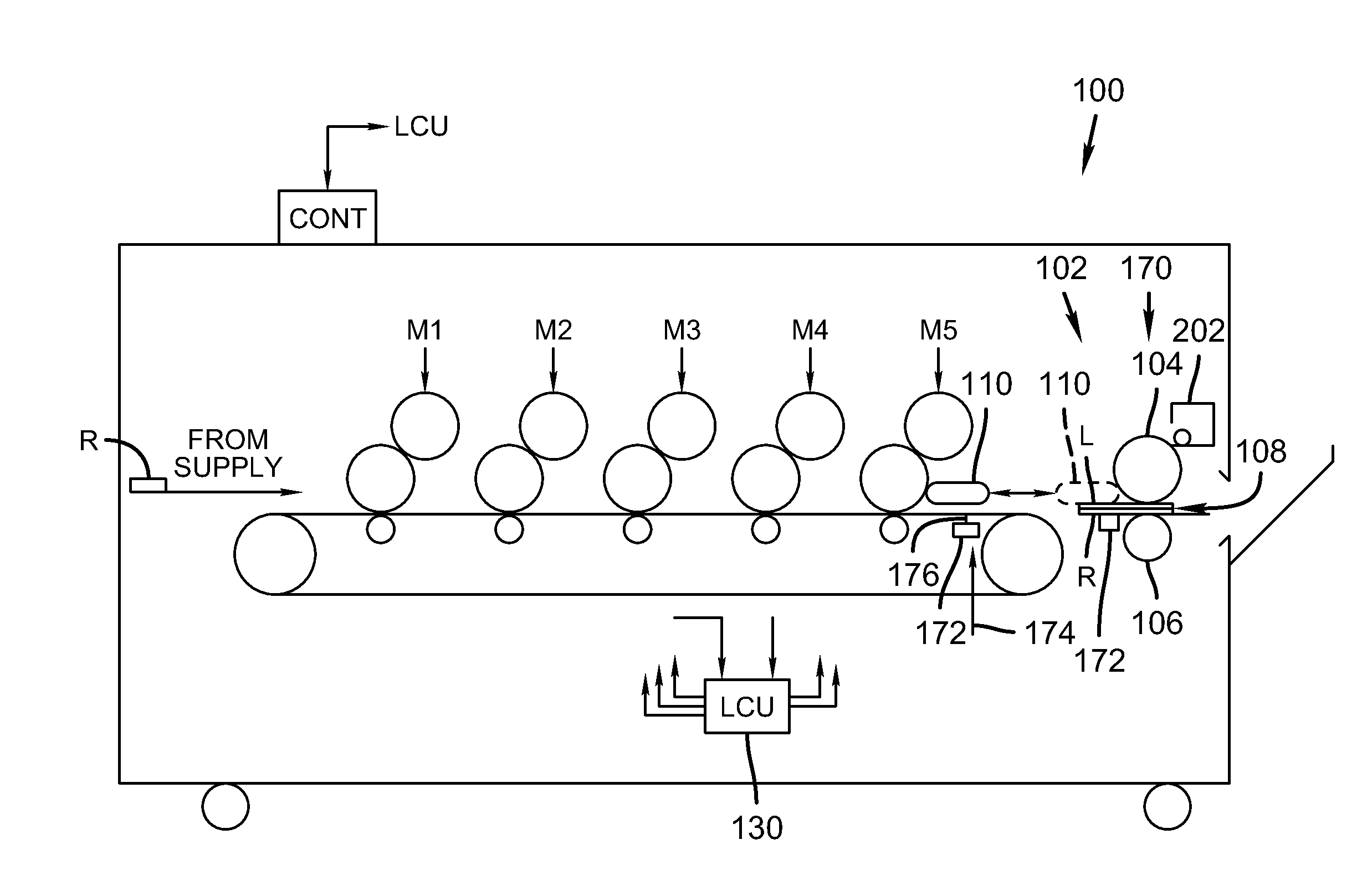
[0020]Throughout the specification and claims the following terms take the meanings explicitly associated herein, unless the context clearly dictates otherwise. The meaning of “a,”“an,” and “the” includes plural reference, the meaning of “in” includes “in” and “on.” The term “connected” means either a direct electrical connection between the items connected or an indirect connection through one or more passive or active intermediary devices. The term “circuit” means either a single component or a multiplicity of components, either active or passive, that are connected together to provide a desired function. The term “signal” means at least one current, voltage, or data signal.

[0021]Additionally, directional terms such as “on”, “over”, “top”, “bottom”, are used with reference to the orientation of the Figure(s) being described. Because components of embodiments of the present invention can be positioned in a number of different orientations, the directional terminology is used for pu...


PUM


Abstract

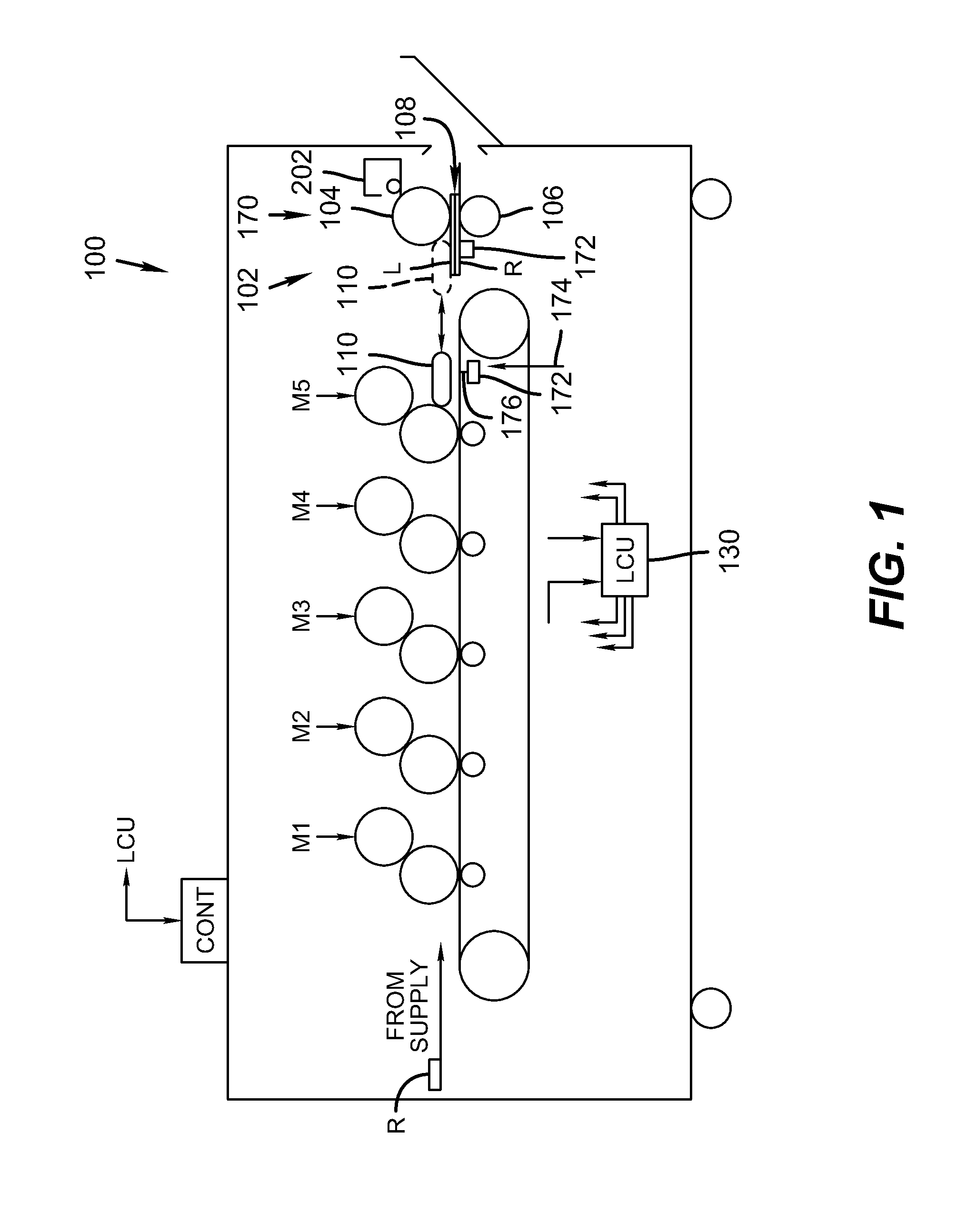
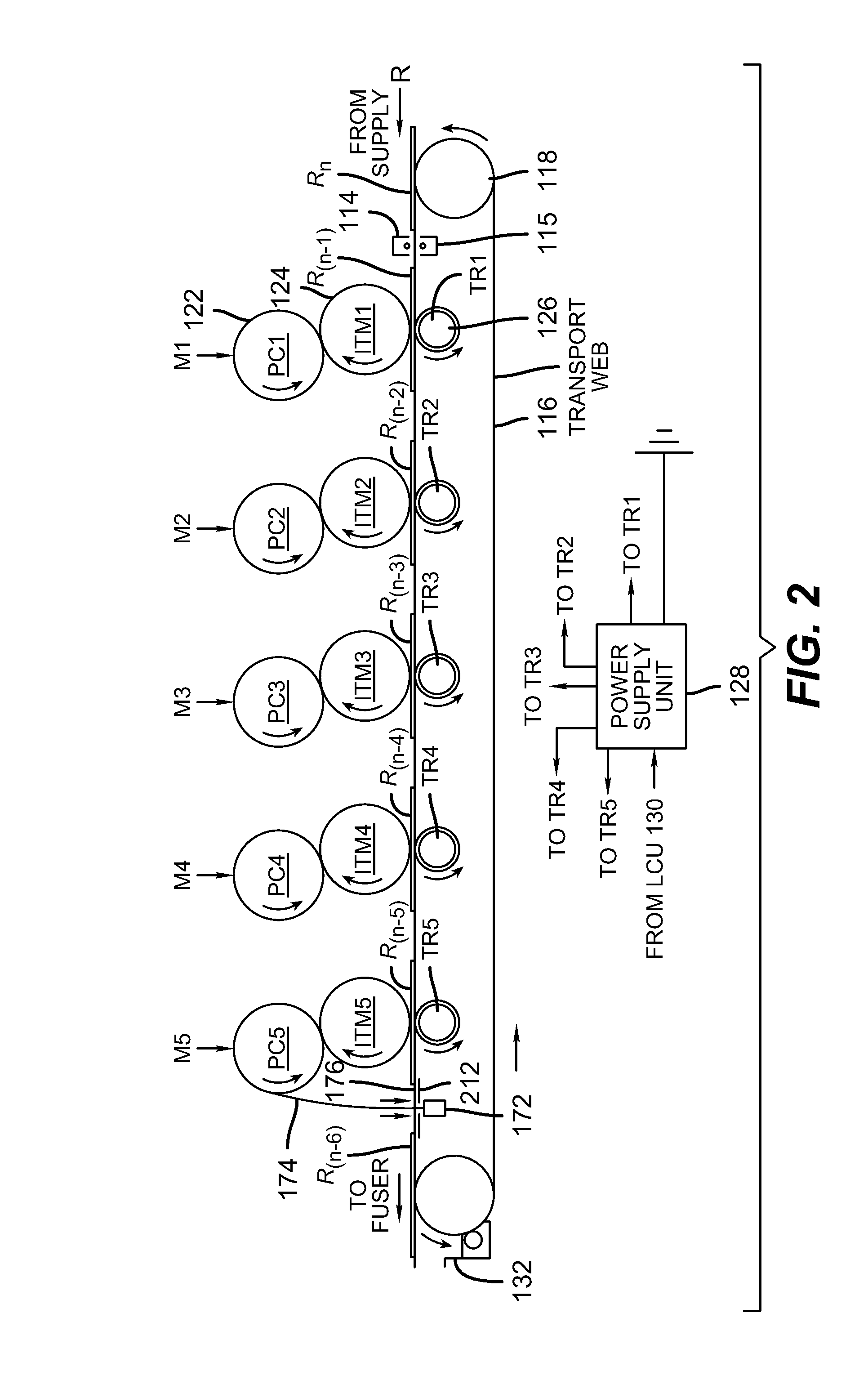
One or more printers or printing systems are connected to a scanning device. Each printer includes one or more color modules that are used during a printing operation. A printer prints a target for each color module or color channel. The printed targets are then scanned by the scanning device. The printed targets may be rotated to any angle and then scanned by the scanning device. The scanned raster data is processed by a controller to detect non-uniformities in at least one density image and to generate one or more correction profiles for the printer. When an image is to be printed, one or more controllers receive the image data and use the one or more correction profiles to correct or compensate for the non-uniformities during the exposure process.

Description

CROSS REFERENCE TO RELATED APPLICATIONS[0001]This application claims the benefit of U.S. Provisional Application No. 61 / 106,172 filed on Oct. 17, 2008, and U.S. Provisional Application No. 61 / 183,992 filed on Jun. 4, 2009, which are incorporated herein by reference.TECHNICAL FIELD[0002]The present invention relates generally to the filed of digitally controlled printing devices, and in particular to devices and methods that improve the image quality of prints produced by these printing devices.BACKGROUND[0003]Digital printing has begun to play an ever-increasing role in the commercial printing industry, and the demand for the capability of digital printing technologies, such as electrophotography, drop-on-demand inkjet, and continuous inkjet, to deliver high quality prints is also increasing. Various image artifacts in the spatial domain, the temporal domain, or the spatial and temporal domains adversely affect image quality. For instance, granularity is defined as the aperiodic non...

Claims


Application Information

Patent Timeline
IPC IPC(8): G06F15/00
CPCG03G15/5062G03G2215/00063H04N1/4015G06K15/1247G03G2215/00067
Inventor KUO, CHUNG-HUITAI, HWAI-TZUUMUNECHIKA, STACY M.SREEKUMAR, CUMARZEISE, ERIC K.FARNAND, STEPHEN J.HENDERSON, THOMAS A.
Owner EASTMAN KODAK CO
Why Eureka
Try Eureka