Battery cooling structure

a battery and cooling structure technology, applied in the field of battery cooling structure, can solve the problems of occupants in vehicles, reduce the cooling efficiency of the battery pack, etc., and achieve the effect of suppressing the effect of preventing the cooling efficiency drop, and suppressing the adverse effect of the exhaust of heated cooling air

Inactive Publication Date: 2010-04-22
TOYOTA JIDOSHA KK
View PDF6 Cites 42 Cited by
  • Summary
  • Abstract
  • Description
  • Claims
  • Application Information

AI Technical Summary

Benefits of technology

[0010]According to the battery cooling structure thus configured, in the partition panel standing away from the rear seat with the clearance therebetween, the air exhaust hole is formed. Accordingly, the air exhausted from the luggage room via the air exhaust hole flows in the clearance between the rear seat and the partition panel and is then brought back to the vehicular cabin. This causes dispersion of the air, and then the air is brought back to the vehicular cabin. Hence, an occupant in the vehicular cabin can be prevented from feeling unpleasant about the high temperature air. Further, the air exhaust hole is formed at the location spaced away from the duct hole. Accordingly, the high temperature air exhausted from the air exhaust hole is less likely to be drawn immediately from the air inlet, whereby decrease of cooling efficiency of the battery can be prevented. Thus, according to the present invention, an adverse effect caused by exhaust of heated cooling air can be suppressed.
[0011]Further, it is preferable that the air exhaust hole be formed at a location higher than the location of the air inlet. According to the battery cooling structure thus configured, the high temperature air exhausted from the air exhaust hole is less likely to travel toward the air inlet, thus achieving further effective suppression of decrease of cooling efficiency of the battery.
[0012]Further, it is preferable that the air inlet and the air exhaust hole be positioned opposite to each other with respect to a center line in a vehicular width direction of the vehicle. According to the battery cooling structure thus configured, the air inlet and the air exhaust hole are positioned away from each other in the vehicular width direction. Accordingly, the air exhausted from the air exhaust hole is less likely to be drawn via the air inlet.
[0013]Further, it is preferable that the air intake duct include a first portion and a second portion divided by the luggage room and connected to each other. According to the battery cooling structure thus configured, with the first portion and the second portion separated, the battery can be installed in the luggage room to improve workability upon installing the battery.
[0014]Further, it is preferable that the battery cooling structure further includes: a fan for distributing the cooling air to the air intake duct; and a frame member, provided in the luggage room, for reinforcing a body of the vehicle. The fan is fixed to the frame member. According to the battery cooling structure thus configured, with the fan fixed to a highly rigid frame member, the vibration of the fan can be prevented from being transferred to the vehicular main body.
[0015]As described above, according to the present invention, a battery cooling structure suppressing an adverse effect caused by exhaust of heated cooling air can be provided.

Problems solved by technology

When such high temperature air is brought back to the vehicular cabin, an occupant in the vehicular cabin may feel unpleasant about the flow of such air, or the high temperature air may be drawn into the luggage room again to decrease the cooling efficiency of the battery pack.

Method used


Image

  • Battery cooling structure
  • Battery cooling structure
  • Battery cooling structure

Examples


Embodiment Construction

[0022]Embodiments of the present invention will be described with reference to figures. It should be noted that the same or equivalent members are given the same reference characters in the figures referenced below.

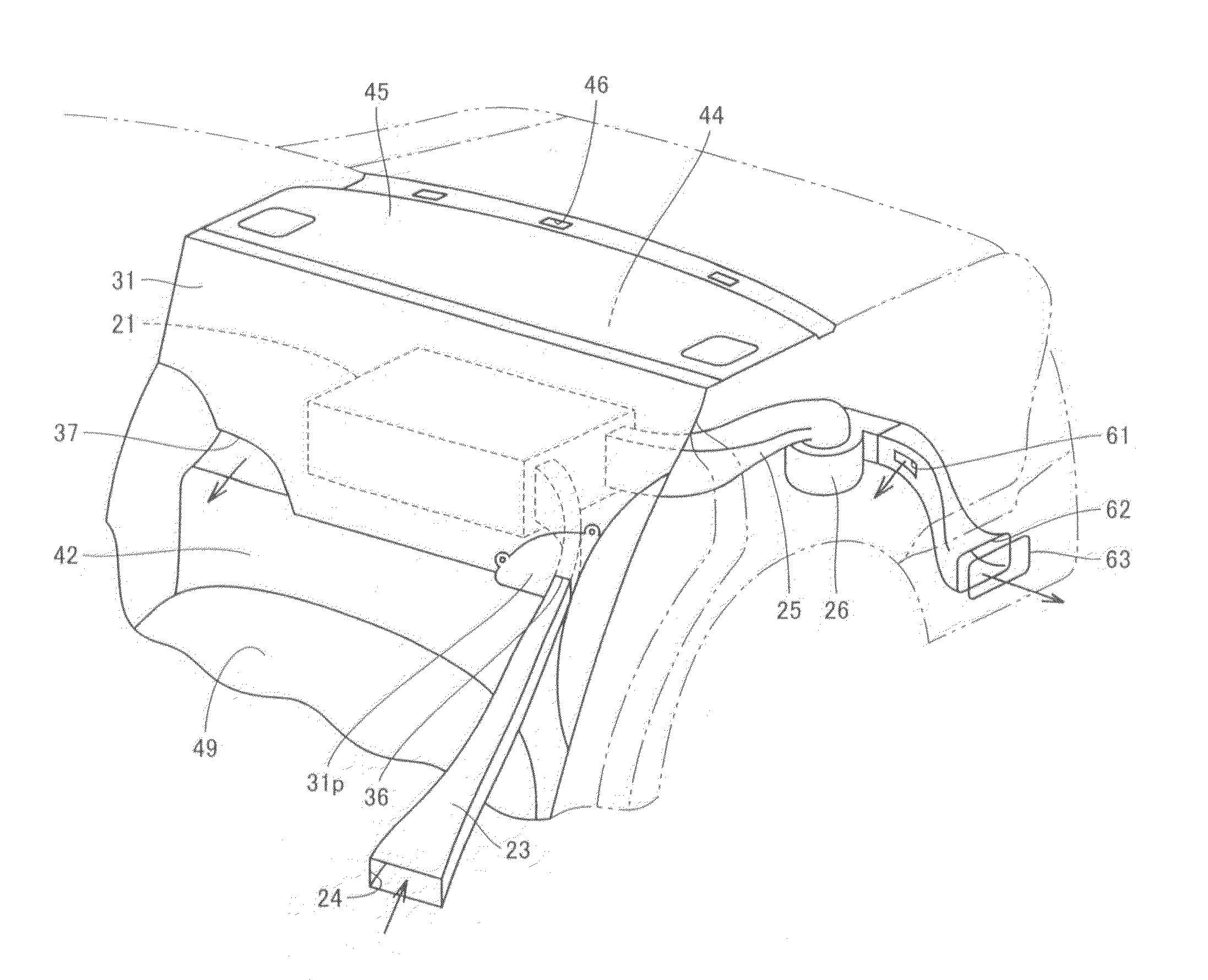
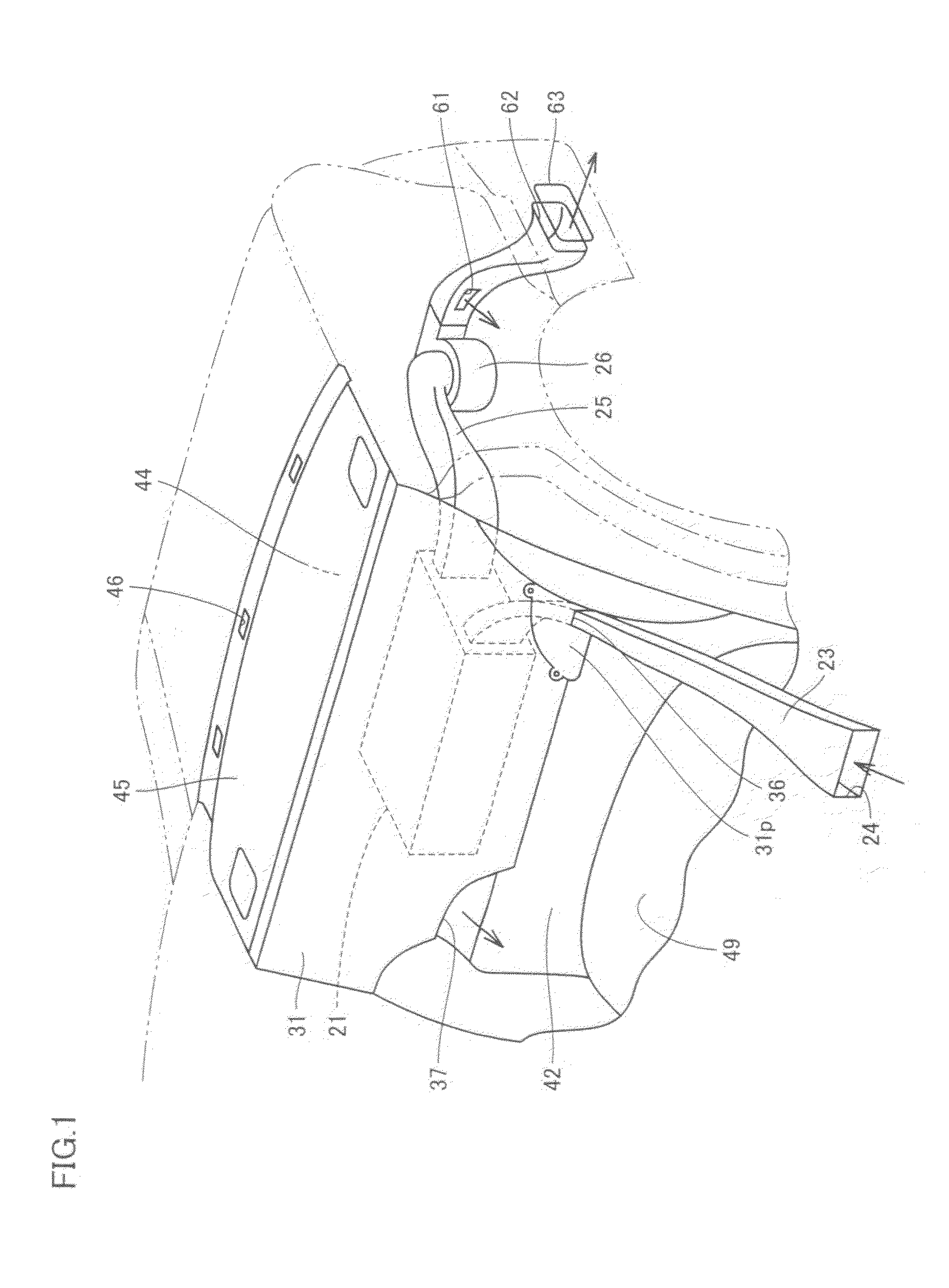
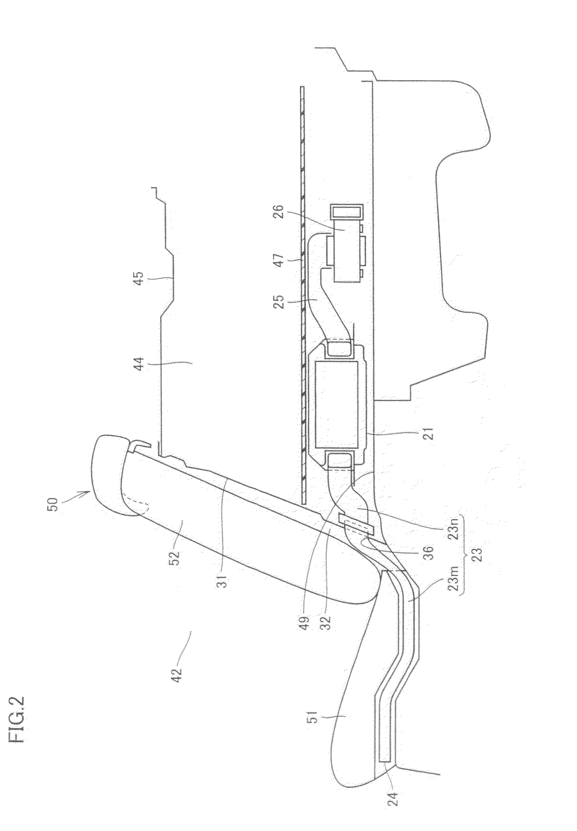
[0023]FIG. 1 is a perspective view showing a hybrid car to which a battery cooling structure of an embodiment of the present invention is applied. In FIG. 1, surroundings of a luggage room of the hybrid car are shown but its rear seat is not illustrated therein. FIG. 2 is a cross sectional view of the hybrid car of FIG. 1.

[0024]Referring to FIG. 1 and FIG. 2, the hybrid car, serving as a vehicle, employs an internal combustion engine such as a gasoline engine or a diesel engine and a vehicle driving motor as motive power sources.

[0025]In the hybrid car, a vehicular cabin 42 and a luggage room 44 are formed. Vehicular cabin 42 is a space in which an occupant resides. Vehicular cabin 42 is provided with a rear seat 50. Rear seat 50 is positioned on a floor 49 that is a bott...


PUM

PropertyMeasurementUnit
widthaaaaaaaaaa
capacitanceaaaaaaaaaa
voltageaaaaaaaaaa

Abstract

A battery cooling structure includes: a battery provided in a luggage room of a vehicle; an air intake duct, including an air inlet open in a vehicular cabin, for supplying air in the vehicular cabin to the battery as cooling air; and a partition panel standing away from a rear seat with a clearance therebetween so as to section the luggage room and the vehicular cabin and provided with a duct hole in which the air intake duct is inserted. The partition panel is provided with an air exhaust hole for exhausting air in the luggage room to the vehicular cabin. The air exhaust hole is formed at a location spaced away from the duct hole. Such a configuration provides a battery cooling structure suppressing an adverse effect caused by exhaust of heated cooling air.

Description

TECHNICAL FIELD[0001]The present invention generally relates to a battery cooling structure, more particularly, a battery cooling structure installed in a luggage room of a vehicle.BACKGROUND ART[0002]Regarding conventional battery cooling structures, for example, Japanese Patent Laying-open No. 2004-1683 (Patent Document 1) discloses a vehicular battery cooling structure to prevent deterioration of battery characteristics and short life thereof. The vehicular battery cooling structure disclosed in Patent Document 1 includes an air intake duct connected to a battery pack, and an air sending fan distributing cooling air to the air intake duct in order to cool the battery pack. The air intake duct is provided with an air inlet located above a tonneau cover for covering a luggage placed in a luggage room.[0003]Further, Japanese Patent Laying-open No. 5-169981 (Patent Document 2) discloses a device, provided in an electric car, for cooling a battery mounted therein by means of external ...

Claims


Application Information

Patent Timeline
Patent Type & Authority Applications(United States)
IPC IPC(8): H01M10/50B60K1/04B60K11/06B60L11/18H01M10/60H01M10/613H01M10/625H01M10/6556H01M10/6563
CPCB60K1/04B60K2001/005B60K2001/0416H01M10/5073H01M10/5016H01M10/5067H01M10/5004H01M10/613H01M10/625H01M10/6563H01M10/6566Y02E60/10
Inventor NAGATA, SHUICHINAGASE, SHUJI
Owner TOYOTA JIDOSHA KK
Why Eureka
Try Eureka