
Serial test mode of an integrated circuit (IC)

a technology of integrated circuits and serial test modes, applied in the field of analysis of electronic circuits, to achieve the effect of reducing the number of pins required

Inactive Publication Date: 2010-04-22
IBM CORP
View PDF13 Cites 10 Cited by
  • Summary
  • Abstract
  • Description
  • Claims
  • Application Information

AI Technical Summary

Benefits of technology

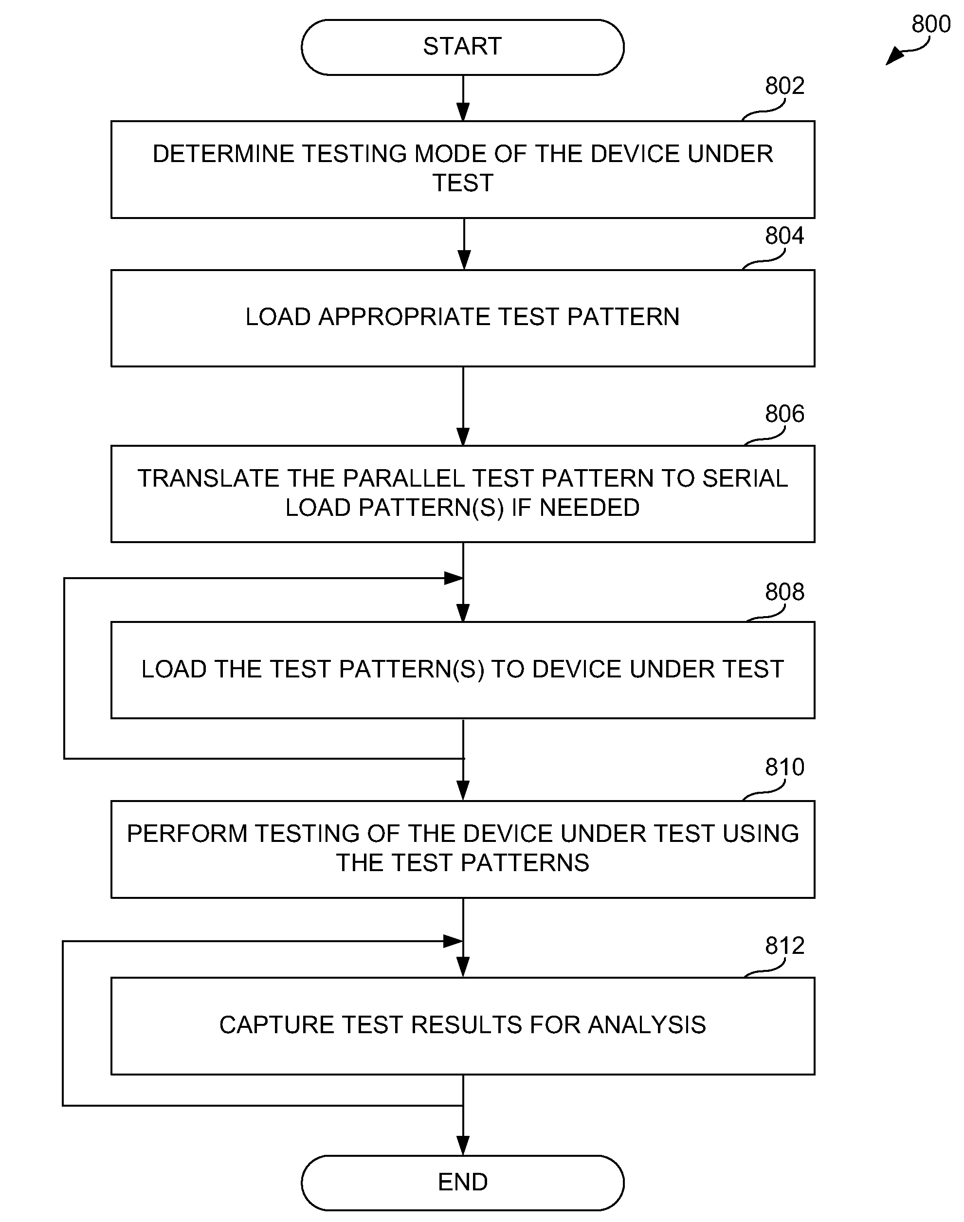
[0008]Embodiments of the present disclosure provide a method of performing serial testing of an integrated circuit (IC) which may be installed within its intended application. This involves loading a parallel test pattern to a first software module. The parallel test pattern is translated to a serial load pattern by the first software module. Then the serial load patterns may be loaded to the device under test such as the IC with a second software module. Testing of the device under test may be performed using the serial load patterns. The test results are captured for analysis. These test results may need to be translated from a serial output format to a parallel output format. Using a serial format in place of a parallel format for testing patterns may greatly reduce the number of pins required to apply test patterns to test structures within the die. This allows testing to be performed on die that have been packaged and assembled within printed circuit boards which may not have previously been possible. Furthermore since this testing might identify faults associated with die after they have been packaged and installed, where redundancy exists, these devices may be reconfigured to take advantage of redundant features within the die based on these test results.

Problems solved by technology

Furthermore since this testing might identify faults associated with die after they have been packaged and installed, where redundancy exists, these devices may be reconfigured to take advantage of redundant features within the die based on these test results.

Method used


Image

  • Serial test mode of an integrated circuit (IC)
  • Serial test mode of an integrated circuit (IC)
  • Serial test mode of an integrated circuit (IC)

Examples


Embodiment Construction

[0021]Preferred embodiments of the present disclosure are illustrated in the FIGs., like numerals being used to refer to like and corresponding parts of the various drawings.

[0022]Embodiments of the present disclosure provide a methodology to perform testing of integrated circuits (IC) wherein a reduced number of Input / Output (IO) pins may used to load testing patterns and capture test results from test structures after an IC has been installed in its intended application. This methodology utilizes a software engine that receives and translates a parallel test pattern into serial data patterns operable to be provided on the reduced number of I / O pins. A serial process loader then loads the serial data patterns to the test structures within the IC. The IC receives the serial patterns and in turn translates them into parallel test patterns in order to apply the test patterns to the appropriate test structures. The results are captured and then translated into a serial format for commu...


PUM


Abstract

A methodology to perform testing of integrated circuits (IC) wherein a reduced number of Input / Output (IO) pins may used to load testing patterns and capture test results from test structures after an IC has been installed in its intended application is provided. This methodology utilizes a software engine that receives and translates a parallel test pattern into serial data patterns operable to be provided on the reduced number of I / O pins. A serial process loader then loads the serial data patterns to the test structures within the IC. The IC receives the serial patterns and in turn translates them into parallel test patterns in order to apply the test patterns to the appropriate test structures. The results are captured and then translated into a serial format for communication from the IC to a test unit for analysis.

Description

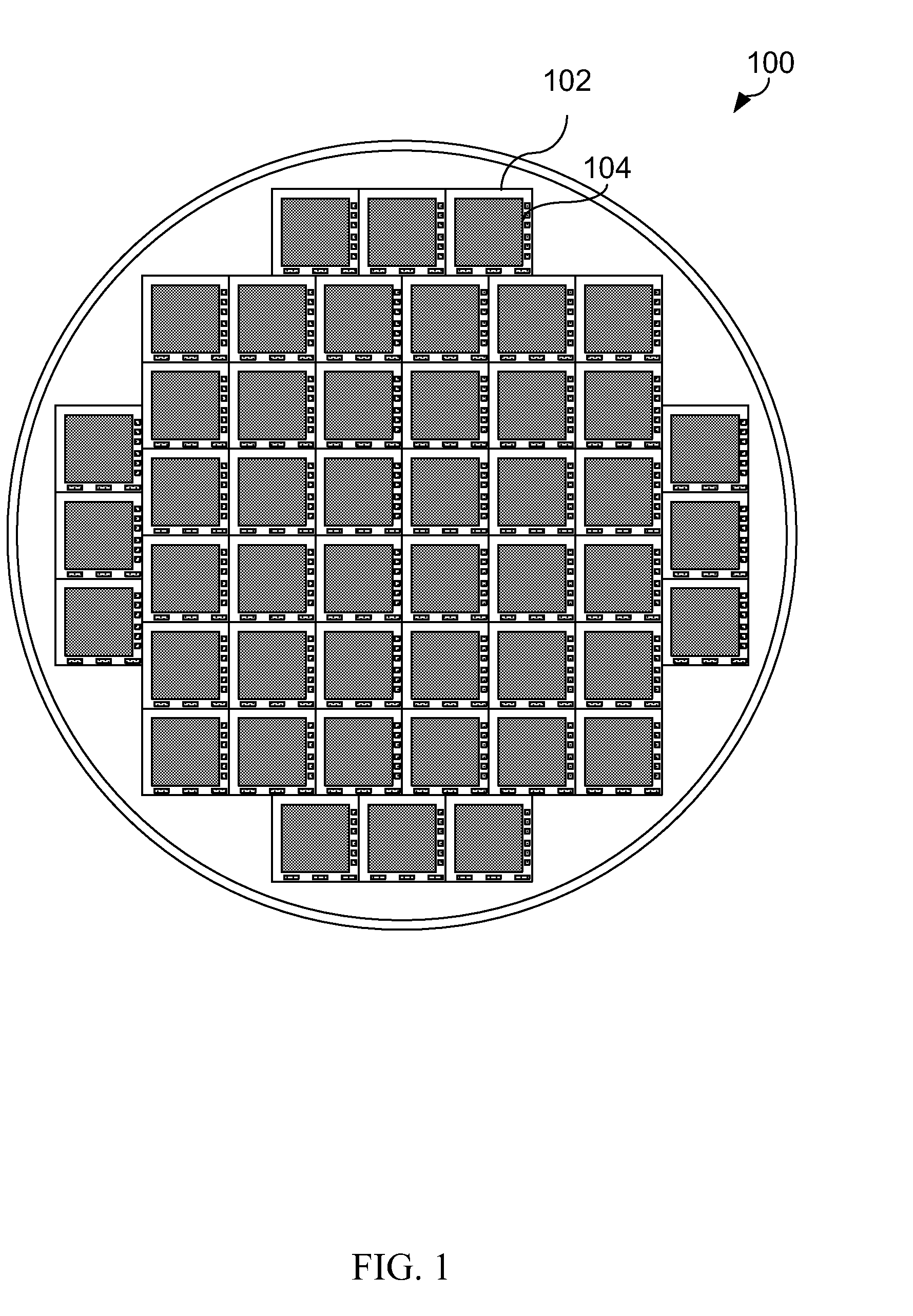
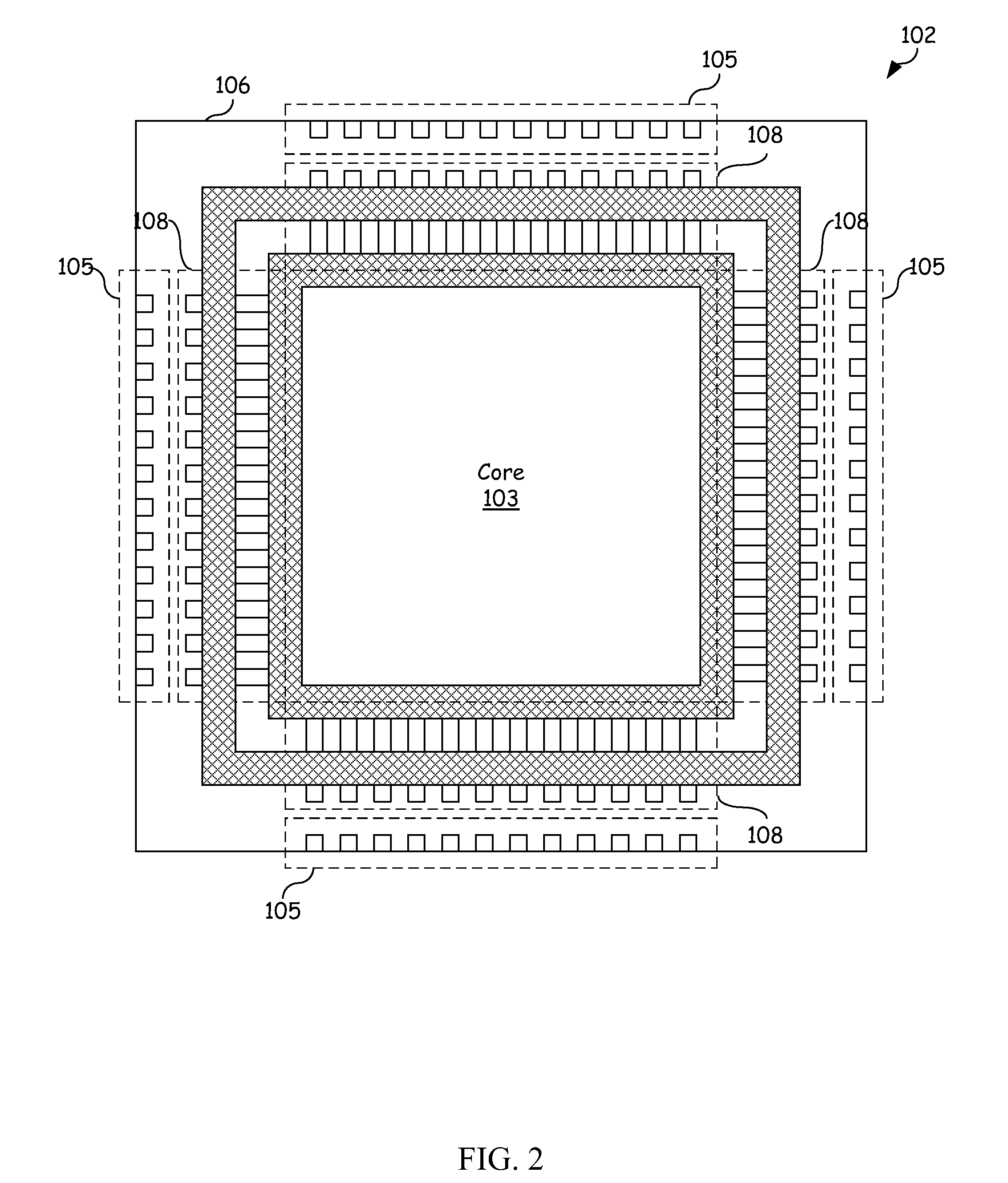
BACKGROUND OF THE INVENTION[0001]The present disclosure relates generally to the analysis of electronic circuits under various conditions, and more particularly, a system and method for analyzing circuitry within an integrated circuit (IC) within an application environment.[0002]As the density of ICs increases, the potential problems associated with manufacturing and fabrication become greater and more difficult to detect. ICs are typically manufactured or fabricated on silicon wafers such as wafer 100 depicted in FIG. 1. Wafer testing involves an electrical test of test structures 104 on each die 102 of wafer 100 to determine if the die 102 will perform as desired.[0003]During testing, before wafer 100 is sent to die preparation and packaging, all individual ICs that are present on the wafer are tested for functional defects with special test patterns. When all test patterns pass for a specific die 102, the dies that pass are remembered for later use during IC packaging. Sometimes ...

Claims


Application Information

Patent Timeline
Patent Type & Authority Applications(United States)
IPC IPC(8): G01R31/3183G06F11/263
CPCG01R31/318511
Inventor DIXON, ROBERT C.DEVOR, ROBERTLE, HIEN M.BIRD, SARAH LYNN
Owner IBM CORP
Learn More