Ball screw device having ball return pipe

a technology of ball return pipe and screw device, which is applied in the direction of gearing, mechanical equipment, hoisting equipment, etc., to achieve the effect of smooth movement, smooth attachment or anchoring, or securing or retaining

Inactive Publication Date: 2010-04-29
HIWIN TECH
View PDF8 Cites 6 Cited by
  • Summary
  • Abstract
  • Description
  • Claims
  • Application Information

AI Technical Summary

Benefits of technology

[0012]The primary objective of the present invention is to provide a ball screw device including a securing or mounting structure for suitably and smoothly attaching or anchoring or securing or retaining a ball return pipe to the ball screw device and for suitably guiding the ball bearing members to smoothly move through the endless ball guiding passages of the ball screw device and the ball return pipe.
[0013]In accordance with one aspect of the invention, there is provided a ball screw device comprising an elongated screw including one or more helical grooves formed therein and including one or more helical teeth formed between the helical grooves of the screw, a nut member including a screw hole formed therein for receiving the screw, and including one or more helical grooves and one or more helical teeth for forming the screw hole of the nut member, and for engaging with the helical grooves and the helical teeth of the screw, and for forming an endless ball guiding passage between the nut member and the screw, and including two orifices formed in the nut member and communicating with the helical grooves of the nut member, a number of ball bearing members engaged in the endless ball guiding passage of the ball screw device, a ball return pipe including a U-shaped structure having a central tubular member, and having two ends for engaging into the orifices of the nut member respectively, and having two curved coupling portions formed between the central tubular member and the ends, and the ball return pipe including a ball return pathway formed therein and communicating with the helical grooves and the endless ball guiding passage of the nut member for receiving the ball bearing members, and the nut member includes a straight fence formed between the orifice and the screw hole of the nut member for guiding the ball bearing members to move through the ball return pathway of the ball return pipe and the endless ball guiding passage of the nut member, and for preventing the helical teeth of the nut member from being broken by the ball bearing members when the ball bearing members are moved in a fast speed through the ball return pathway of the ball return pipe and the endless ball guiding passage of the ball screw device.
[0017]A ball coupler device may further be provided and include one or more longitudinal and parallel connecting members, and a number of spacers secured to the connecting members and spaced from each other for forming a number of compartments between the spacers and for suitably receiving the ball bearing members and for stably and solidly coupling the ball bearing members together and for guiding the ball bearing members to smoothly move through the ball return pathway of the ball return pipe and the endless ball guiding passage of the nut member.

Problems solved by technology

However, the ball return pipe may not be precisely secured to the nut, and the tubular tongues of the ball return pipe may not be precisely directed toward the endless ball guiding passage of the ball screw device, or the ball return pipe may not be precisely meshed with the nut such that one or more projections or protrusions may be extended into the endless ball guiding passage of the ball screw device and may interfere the movement of the ball bearing members through the endless ball guiding passage of the ball screw device.
However, similarly, the ball return pipe may not be precisely secured to the nut, and the tubular tongues of the ball return pipe may not be precisely directed toward the endless ball guiding passage of the ball screw device, or the ball return pipe may not be precisely meshed with the nut such that one or more projections or protrusions may be extended into the endless ball guiding passage of the ball screw device and may interfere the movement of the ball bearing members through the endless ball guiding passage of the ball screw device.
However, the ball return pipe may not be precisely secured to the nut, and the tubular tongues of the ball return pipe may not be precisely directed toward the endless ball guiding passage of the ball screw device, or the ball return pipe may not be precisely meshed with the nut such that one or more projections or protrusions may be extended into the endless ball guiding passage of the ball screw device and may interfere the movement of the ball bearing members through the endless ball guiding passage of the ball screw device, and may be broken by the ball bearing members when the ball bearing members are moved in a fast speed through the endless ball guiding passage of the ball screw device.

Method used


Image

  • Ball screw device having ball return pipe
  • Ball screw device having ball return pipe
  • Ball screw device having ball return pipe

Examples


Embodiment Construction

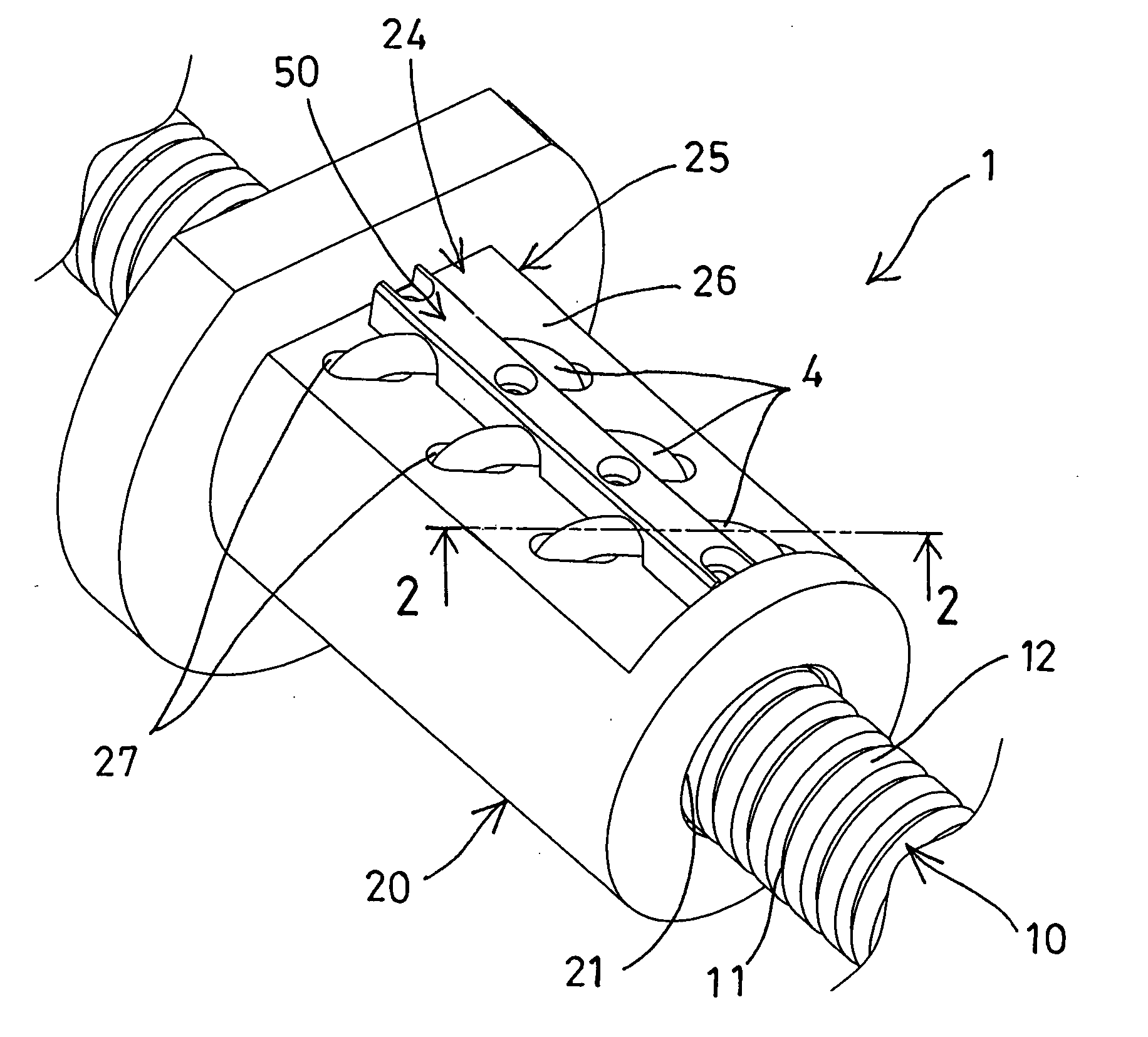
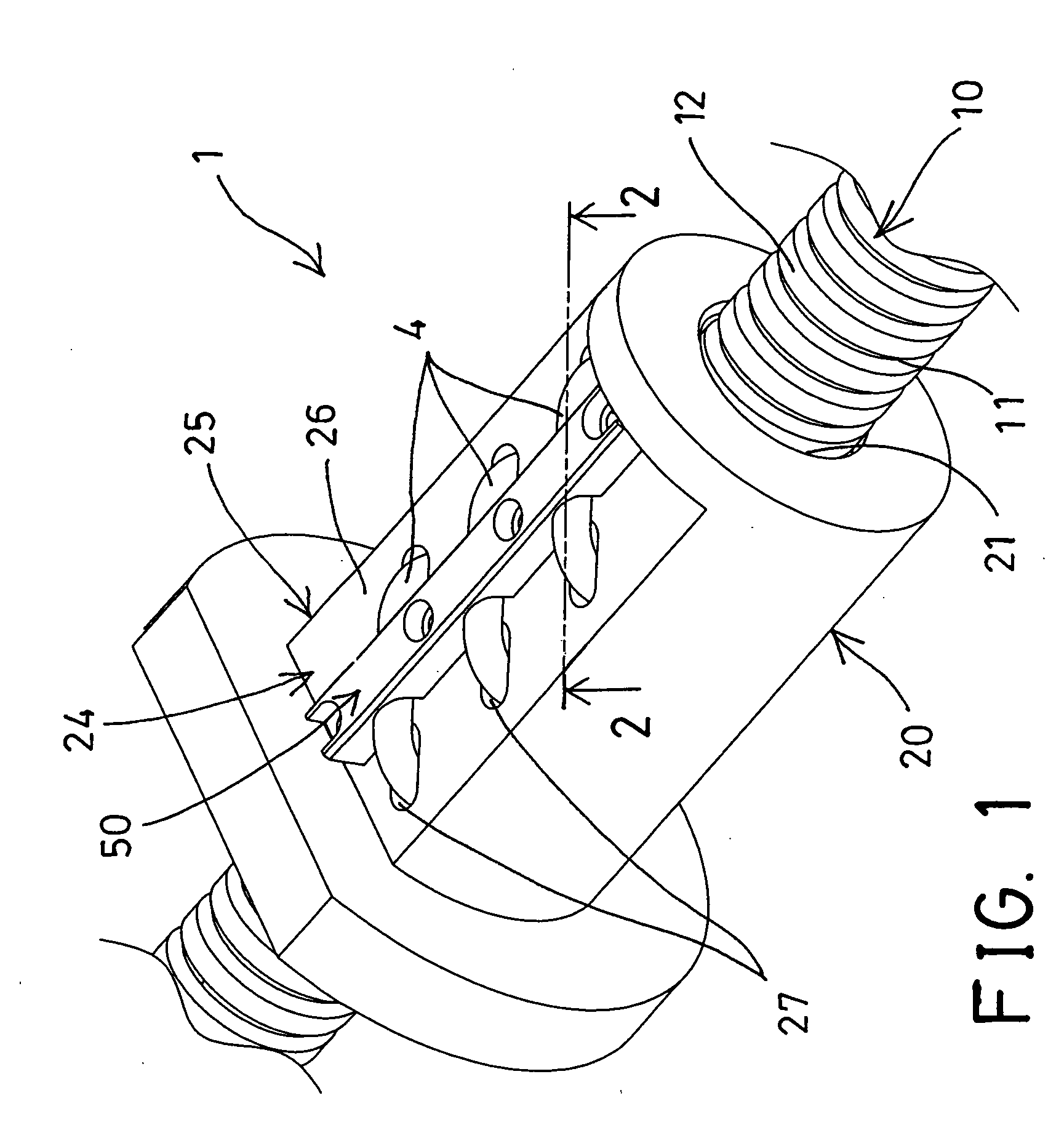
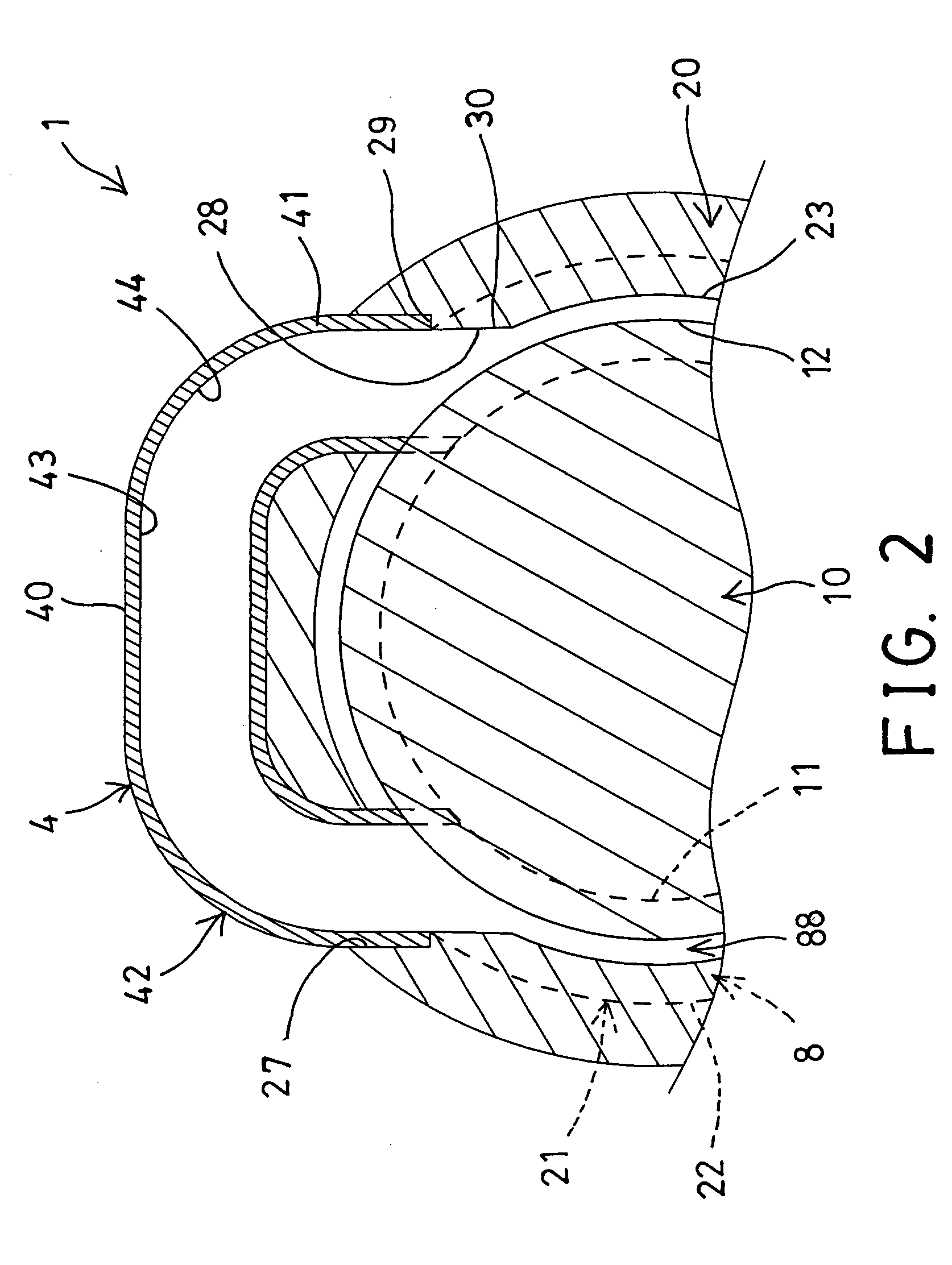
[0026]Referring to the drawings, and initially to FIGS. 1-4, a ball screw device 1 in accordance with the present invention comprises an elongated bolt or screw 10 including one or more helical threaded portions or grooves 11 formed therein and / or including one or more helical teeth 12 formed between the helical threaded portions or grooves 11 of the screw 10, and comprises a nut member 20 including a screw hole 21 formed therein for threading or engaging with the screw 10, and for allowing the nut member 20 to be rotated and moved or adjusted along the screw 10. The nut member 20 also includes one or more helical threaded portions or grooves 22 formed therein and / or including one or more helical teeth 23 formed between the helical threaded portions or grooves 22 of the nut member 20.

[0027]The helical threaded portions or grooves 22 and / or the helical teeth 23 of the nut member 20 may be threaded or engaged with the corresponding helical teeth 12 and / or the helical threaded portions...


PUM


Abstract

A ball screw device includes a screw engaged into a nut member for forming an endless ball guiding passage between the nut member and the screw and for receiving a number of ball bearing members, a ball return pipe includes a U-shaped structure having a central tubular member and two ends for engaging into two orifices of the nut member, and the nut member includes a straight fence formed between the orifice and the screw hole of the nut member for guiding the ball bearing members to move through a ball return pathway of the ball return pipe and the endless ball guiding passage of the nut member and for preventing the teeth of the nut member from being broken by the ball bearing members.

Description

BACKGROUND OF THE INVENTION[0001]1. Field of the Invention[0002]The present invention relates to a ball screw device, and more particularly to a ball screw device including a securing or mounting structure for suitably and smoothly attaching or anchoring or securing or retaining a ball return pipe to the ball screw device and for suitably guiding the ball bearing members to smoothly move through the endless ball guiding passages of the ball screw device and the ball return pipe.[0003]2. Description of the Prior Art[0004]Typical ball screw devices comprise a nut threaded onto an elongated bolt or screw and rotatable and movable or adjustable along the screw, one or more endless ball guiding passages formed in the ball screw device for slidably receiving ball bearing members, and one or more ball return pipes attached onto the ball screw device for guiding the ball bearing members to smoothly and suitably move through the endless ball guiding passages of the ball screw device.[0005]Fo...

Claims


Application Information

Patent Timeline
Patent Type & Authority Applications(United States)
IPC IPC(8): F16H25/22F16C29/06
CPCY10T74/19767F16H25/2214
Inventor KUO, CHANG HSINCHIANG, TSUNG SHIEN
Owner HIWIN TECH
Why Eureka
Try Eureka