Heat transfer plate and method of manufacturing the same
heat exchange technology, applied in the field of manufacturing a heat transfer plate, can solve the problems of heat release, difficult to be transferred, and reduce the heat exchange efficiency of the heat transfer plate, and achieve the effects of increasing heat conductivity, high heat exchange efficiency, and large strength of the joining portion
- Summary
- Abstract
- Description
- Claims
- Application Information
AI Technical Summary
Benefits of technology
Problems solved by technology
Method used
Image
Examples
first embodiment
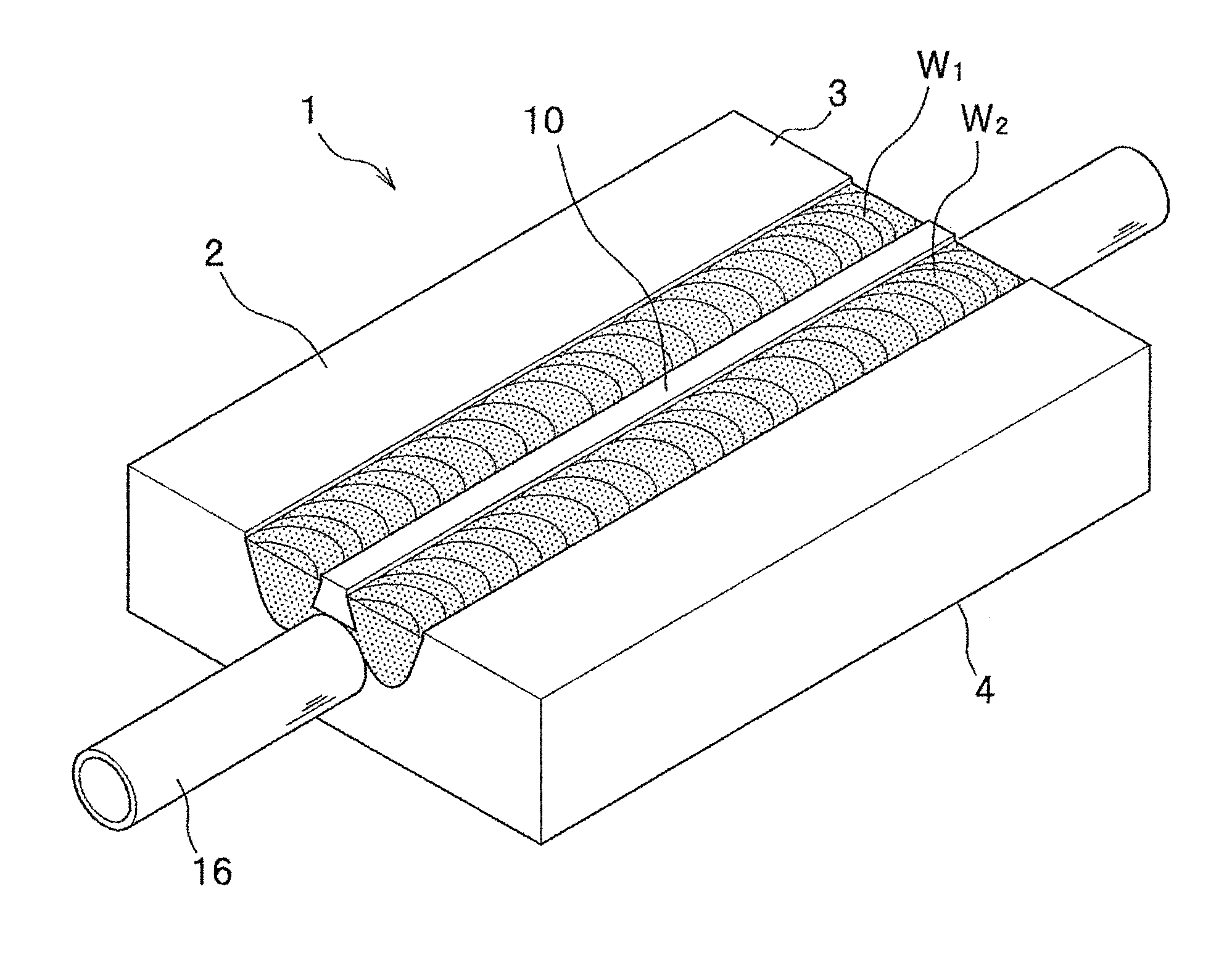
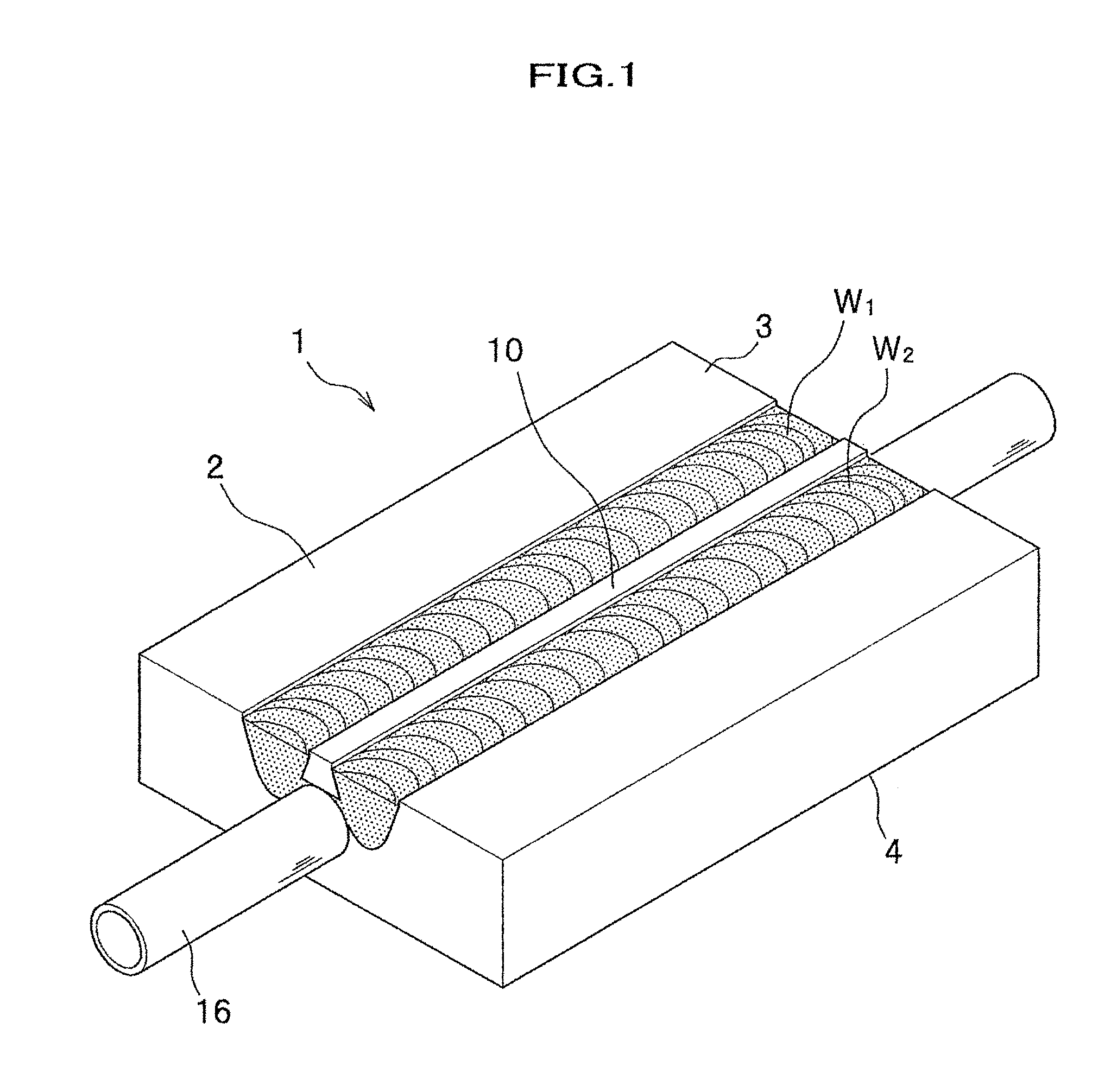
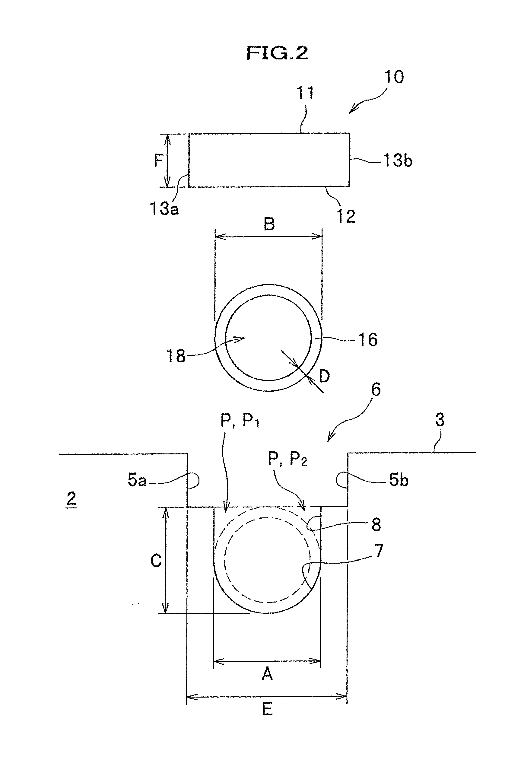
[0062]A best mode of the present invention will be described with reference to drawings. FIG. 1 is a perspective view showing a heat transfer plate relating to a first embodiment of the present invention. FIG. 2 is an exploded side view showing the heat transfer plate relating to the first embodiment. FIG. 3 is an enlarged side view showing the heat transfer plate relating to the first embodiment.
[0063]A heat transfer plate 1 relating to the first embodiment mainly comprises, as shown in FIGS. 1-3, a base member 2 of a thick plate form having an obverse 3 and a reverse 4, a lid plate 10 arranged in a lid groove 6 open to the obverse 3 of the base member 2, and a heat medium pipe 16 inserted in a concave groove 8 open to a bottom face of the lid groove 6; and is integrally formed by plasticized regions W1, W2 formed by friction stirring joining. Moreover, in the heat transfer plate 1, as shown FIGS. 2 and 3, a plastic fluidized material Q is flowed in an air gap portion P formed by t...
second embodiment
[0096]Next will be described a heat transfer plate relating to a second embodiment of the invention. FIG. 7 is an exploded side view showing a heat transfer plate relating to the second embodiment. FIG. 8 is a side view showing the heat transfer plate relating to the second embodiment. A heat transfer plate 31 relating to the second embodiment shown in FIG. 8 is different from the first embodiment in a point that: the plate 31 includes a structure approximately equivalent to the heat transfer plate 1 described above; further arranges an upper lid plate 40 on an obverse of the lid plate 10; and friction stirring joining is applied and joined.
[0097]In addition, the structure equivalent to the heat transfer plate 1 described above is hereinafter also referred to as a lower lid portion M. Furthermore, with respect to a member repeating that of the heat transfer plate 1 relating to the first embodiment, an equivalent symbol will be added and a duplicate description will be omitted.
[0098]...
third embodiment
[0109]A third embodiment of the invention will be described in detail with reference to drawings. FIG. 9 is a perspective view showing a heat transfer plate relating to the third embodiment. FIG. 10 is an exploded side view showing the heat transfer plate relating to the third embodiment. FIG. 11 is a side view showing the heat transfer plate relating to the third embodiment.
[0110]A heat transfer plate 1A relating to the third embodiment mainly comprises, as shown in FIGS. 9-11, the base member 2 of a thick plate having the obverse 3 and the reverse 4; the lid plate 10 arranged in the lid groove 6 open to the obverse 3 of the base member 2; and the heat medium pipe 16 inserted in the concave groove 8 open to a bottom face of the lid groove 6. The base member 2 and the lid plate 10 are integrally formed by plasticized regions W5, W6 formed by means of friction stirring joining. Here, it is assumed that a “plasticized region” includes both states: a state of being heated due to fricti...
PUM
| Property | Measurement | Unit |
|---|---|---|
| Distance | aaaaa | aaaaa |
| Diameter | aaaaa | aaaaa |
| Size | aaaaa | aaaaa |
Abstract
Description
Claims
Application Information
 - R&D
- Intellectual Property
- Life Sciences
- Materials
- Tech Scout
- Unparalleled Data Quality
- Higher Quality Content
- 60% Fewer Hallucinations
Browse by: Latest US Patents, China's latest patents, Technical Efficacy Thesaurus, Application Domain, Technology Topic, Popular Technical Reports.
© 2025 PatSnap. All rights reserved.Legal|Privacy policy|Modern Slavery Act Transparency Statement|Sitemap|About US| Contact US: help@patsnap.com


