Screw cap, container body and container

a screw cap and container body technology, applied in the field of screw caps, can solve the problems of time-consuming and complex manufacturing of screw caps, and achieve the effects of reliable and strong guidance of screw caps, reliable demoulding, and avoiding any shifting or tilting of screw caps

Active Publication Date: 2010-04-29
AIRNOV INC
View PDF16 Cites 15 Cited by
  • Summary
  • Abstract
  • Description
  • Claims
  • Application Information

AI Technical Summary

Benefits of technology

[0039]In order to provide for a reliable and strong guidance of the cap during demoulding, and in particular for avoiding any shifting around or tilting of the cap during demoulding, the cap is guided on a central pin that preferably sits in the desiccant chamber. In this manner, a reliable demoulding can be achieved when forcibly ejecting the cap from the mould.

Problems solved by technology

This screw cap of the prior art comprises an integral full thread, the manufacturing of which is complex and time consuming because a separate moulding insert / element for forming the thread needs to be removed from the finished product during demoulding by un-screwing it.

Method used


Image

  • Screw cap, container body and container
  • Screw cap, container body and container
  • Screw cap, container body and container

Examples


Embodiment Construction

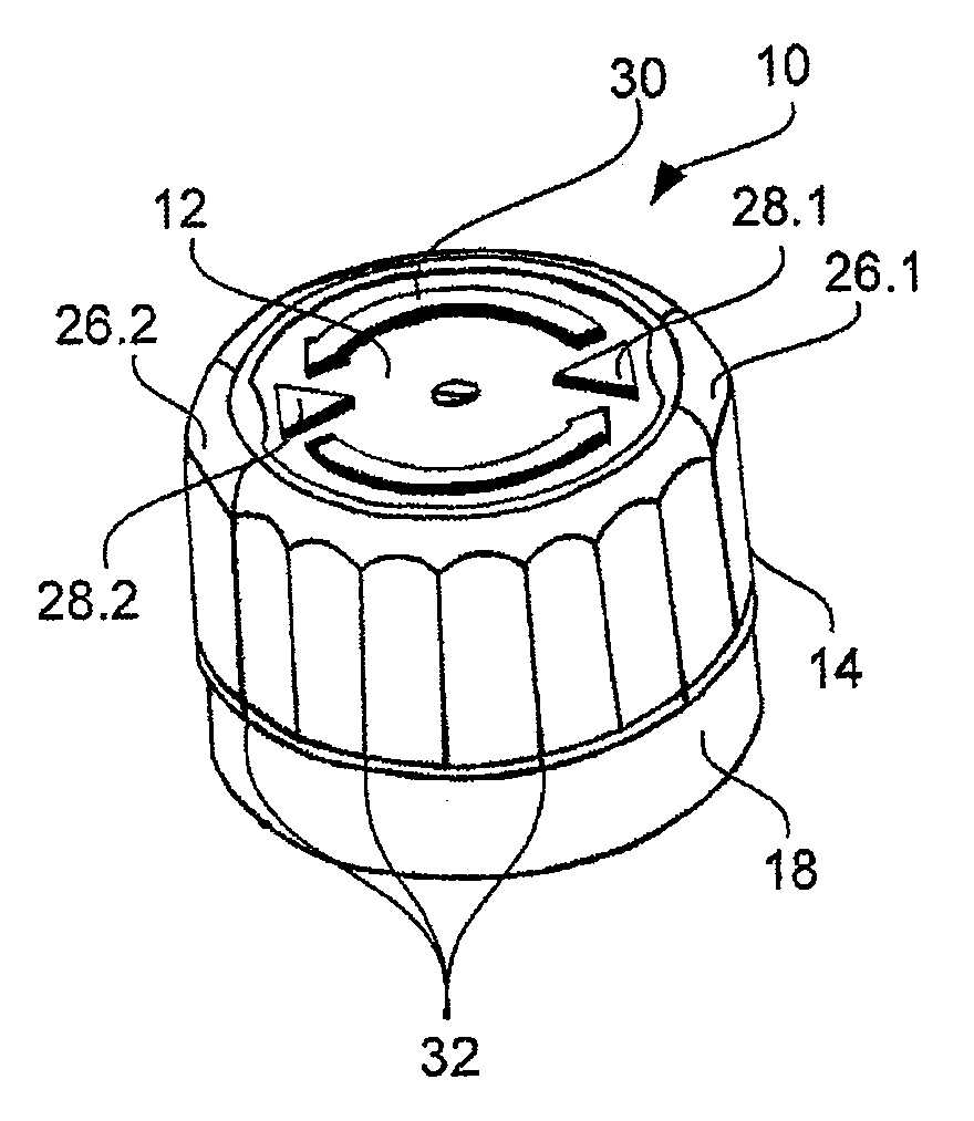
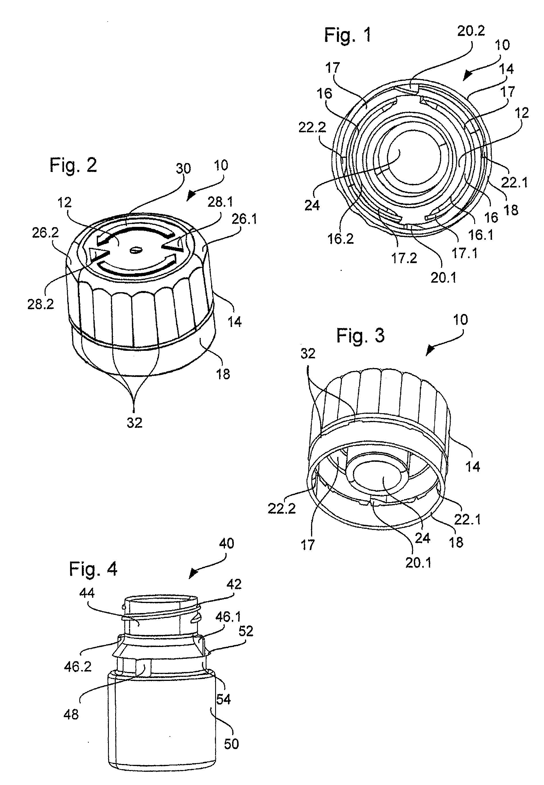
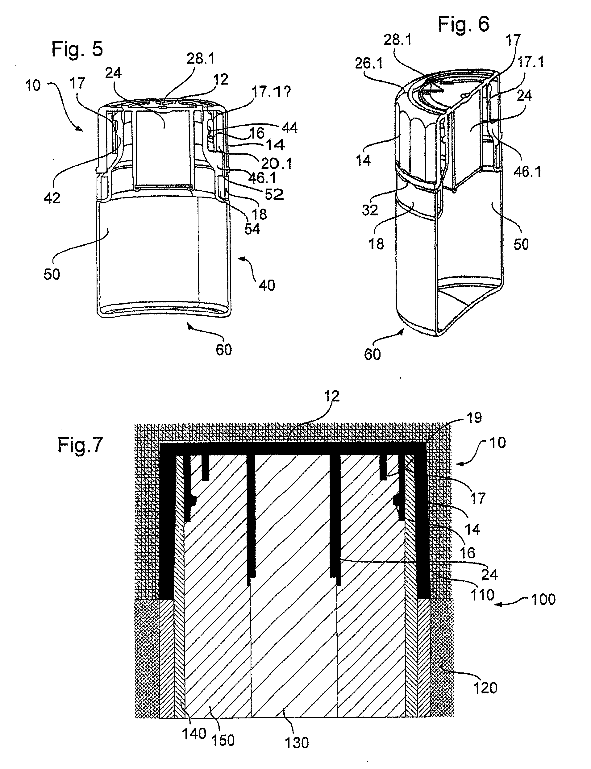
[0054]In the following, a screw cap 10, a container body 40 and a container 60 is described as an exemplary but preferred embodiment.

[0055]FIGS. 1 to 3 show the screw cap 10 according to the embodiment. The screw cap 10 comprises a substantially circular front side wall 12 and a substantially cylindrical peripheral wall 14 which together constitute the outer appearance of the screw cap 10.

[0056]A substantially cylindrical screw section 17, which is, in this embodiment, composed of two distinct skirt portions 17.1 and 17.2, is provided radially inwardly from the peripheral wall 14. Each of the skirt portions 17.1 and 17.2 carries a section of a screw thread 16, namely thread sections 16.1 and 16.2. The screw section 17 is intended to provide the locking engagement between the respective thread sections 16.1 and 16.2 of the screw cap 10 and the container body 40 shown in FIG. 4 and as explained below. The screw section 17 is radially resilient due to its specific design.

[0057]Each of ...


PUM

PropertyMeasurementUnit
radiusaaaaaaaaaa
radiusaaaaaaaaaa
demoulding angleaaaaaaaaaa

Abstract

The invention relates to a screw cap (10) capable of being screwed onto the neck (44) of a container body (40), the screw cap comprising a substantially cylindrical screw section (17) comprising a screw thread (16) on its inner face, at least one tamper evidence member (18) for indicating an initial opening of the screw cap (10), and a desiccant chamber (24) located radially inwardly to the screw section, wherein the screw section (17) is radially resilient.

Description

TECHNICAL FIELD[0001]The invention relates to a screw cap capable of being screwed onto the neck of a container body, to a container body, to a container including the screw cap and to a method for fabricating the screw cap.TECHNICAL BACKGROUND[0002]Closures having a tamper indicating band which is detached from the closure after its first removal from a container are known in the prior art.[0003]WO 98 / 50283, for example, describes a child resistant closure which is, on the one hand, childproof and, on the other hand, comprises a tamper indicating element. This prior art document shows a screw cap which, in the closed state, can only be turned when squeezing two diametrical faces of the cap such that the cap is deformed and the child resistant locking mechanism is overridden. The locking mechanism described in this document comprises two protrusions pointing outwardly from the neck of the container and two further protrusions pointing inwardly from an inside face of the screw cap. T...

Claims


Application Information

Patent Timeline
Patent Type & Authority Applications(United States)
IPC IPC(8): B65D1/02B65D41/00B29D1/00
CPCB29C45/4407B29L2031/565B65D2101/0023B65D51/30B65D50/046B65D2401/15
Inventor SEBILLE, VINCENTPORTIER, BENOITLEBON, JACQUYLOGEL, VALERE
Owner AIRNOV INC
Why Eureka
Try Eureka