Method for separating mold and device for separating mold
A demoulding device and demoulding technology, applied in the field of demoulding and demoulding devices, can solve the problems of long contact time, unreliable demoulding, difficulty in determining the casting sequence, etc., and achieve the effect of reliable demoulding
- Summary
- Abstract
- Description
- Claims
- Application Information
AI Technical Summary
Problems solved by technology
Method used
Image
Examples
Embodiment approach 1
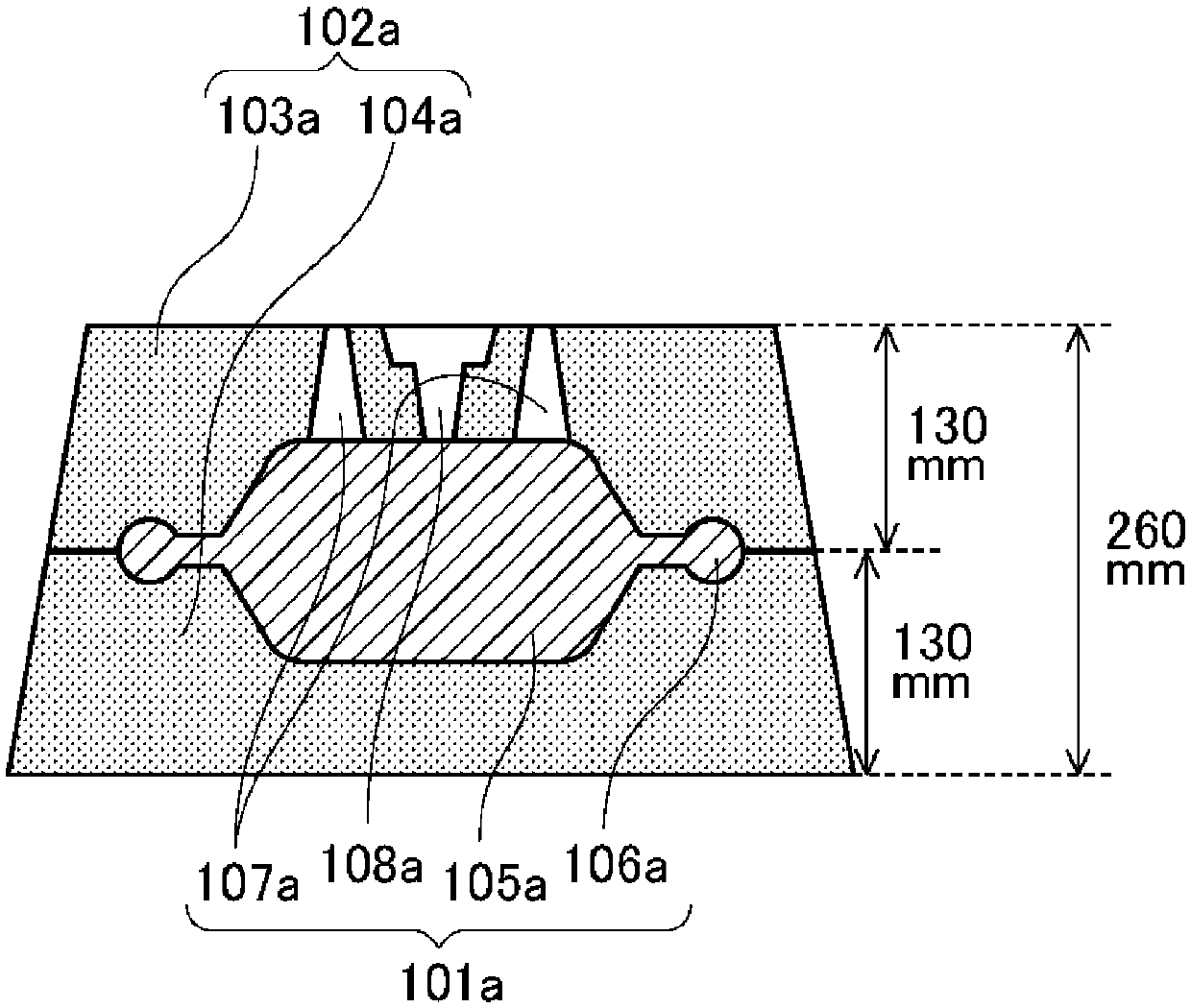
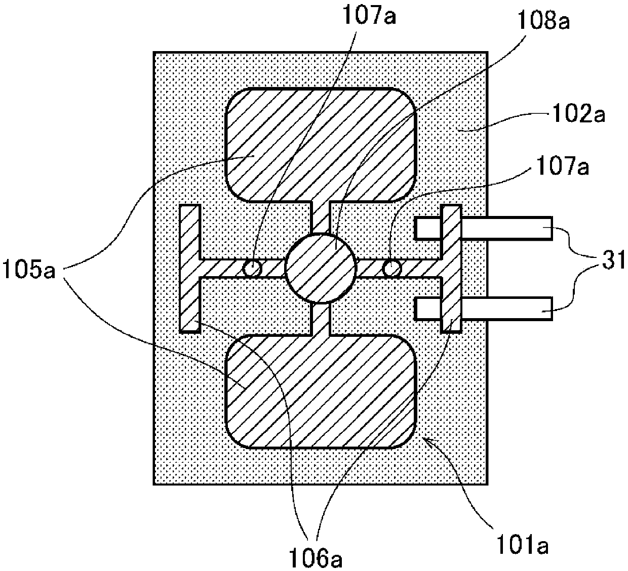
[0071] Figure 1A It is a figure which shows an example of the height of the casting mold put into the demolding apparatus of this embodiment, and the casting formed in the casting mold. Figure 1A The mold 102a shown includes an upper mold 103a and a lower mold 104a between which a casting 101a is formed. The casting 101a has a casting 105a and lugs 106a as products. In addition, in Figure 1A In , the case where the maximum height of the upper mold 103a and the lower mold 104a are both 130mm and the height of the mold 102a is 260mm is exemplified. In addition, the upper mold 103a and the lower mold 104a abut against each other at their respective portions having the greatest height, thereby sealing the casting 101a. The protruding portion 107a and the casting portion 108a will be described later.
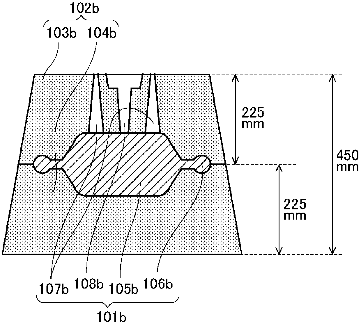
[0072] Figure 1B It is a figure which shows another example of the height of the casting mold put into the demolding apparatus of this embodiment, and the casting formed in ...
Embodiment approach 2
[0093] In the first embodiment, the angle of the table including the mounting surface of the casting mold is adjusted to adjust the relative position of the lug hook portion and the lug portion of the casting, but the present invention is not limited to Therefore, as described in the description of this embodiment, the table can also be moved up and down.
[0094] Compared with Embodiment 1, this embodiment differs only in the adjustment of the relative position of the lug hook portion and the lug portion of the casting, and the other structures are the same as Embodiment 1. Therefore, reference is made to FIGS. 1 to 4 . instruction of.
[0095] Image 6 yes means Figure 4A A detailed side view of this embodiment of the process shown. Image 6 The shown casting mold 102 is placed on a table 32 , and the height of the movable table 32 can be adjusted by extending and contracting an air cylinder 38 a provided on the back side of the table 32 . The cylinder 38a expands and c...
Embodiment approach 3
[0102] In the first embodiment, the angle of the workbench is adjusted to adjust the relative position of the lug hook part and the lug part of the casting. In the second embodiment, the workbench is moved up and down to Although the relative position of the lug hook part and the lug part of a casting is adjusted, the present invention is not limited thereto, and the lug hook part may be moved as described in the description of this embodiment.
[0103] Compared with Embodiments 1 and 2, this embodiment differs only in the adjustment of the relative position of the lug hook portion and the lug portion of the casting. Other than that, the structure is the same as Embodiment 1. Therefore, reference is made to FIGS. Description of Figure 4.
[0104] Figure 7 yes means Figure 4A A detailed side view of this embodiment of the process shown. Figure 7 The illustrated mold 102 is placed on the table 32 . The position of the ear hook part 31a can be adjusted by extending and con...
PUM
 Abstract
Description
Claims
Application Information
 - R&D
- Intellectual Property
- Life Sciences
- Materials
- Tech Scout
- Unparalleled Data Quality
- Higher Quality Content
- 60% Fewer Hallucinations
Browse by: Latest US Patents, China's latest patents, Technical Efficacy Thesaurus, Application Domain, Technology Topic, Popular Technical Reports.
© 2025 PatSnap. All rights reserved.Legal|Privacy policy|Modern Slavery Act Transparency Statement|Sitemap|About US| Contact US: help@patsnap.com


