Die device

A technology of molds and control devices, applied in the directions of forming tools, manufacturing tools, transportation and packaging, etc., can solve the problem of inability to demold the workpiece, and achieve the effect of reliable demoulding

Active Publication Date: 2021-09-28
HONDA MOTOR CO LTD
View PDF8 Cites 0 Cited by
  • Summary
  • Abstract
  • Description
  • Claims
  • Application Information

AI Technical Summary

Problems solved by technology

In this type of mold, there is no space for the lower mold to fully retract the movable mold (movable mold) that avoids the undercut, and it may not be possible to release the workpiece from the mold

Method used


Image

  • Die device
  • Die device
  • Die device

Examples


no. 1 approach

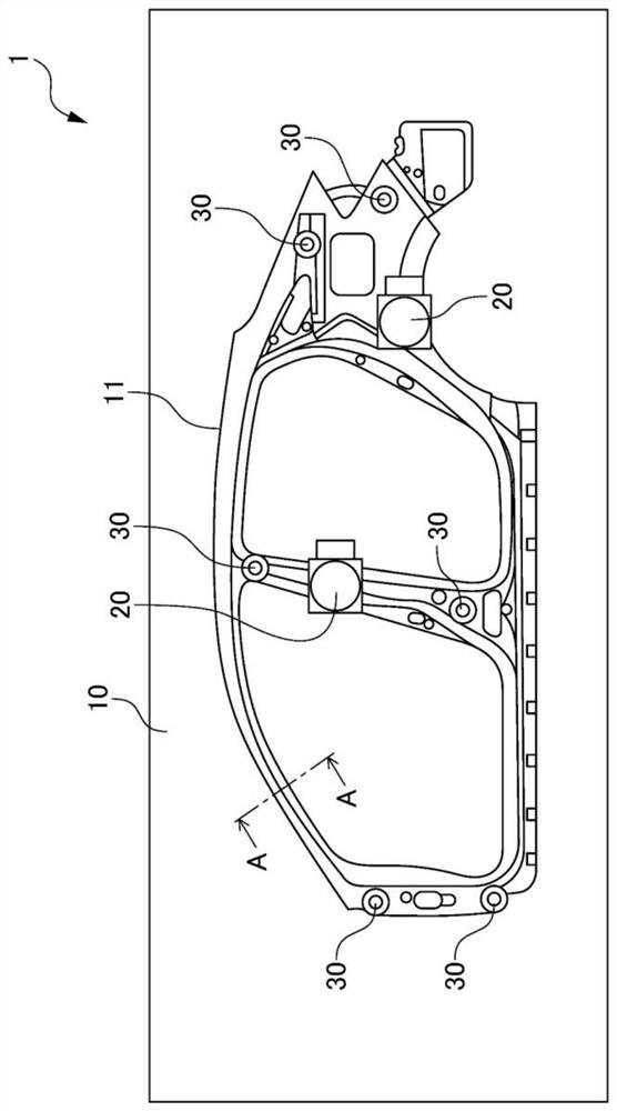
[0032] figure 1 is a diagram showing a first embodiment of the mold device 1 according to the present invention.

[0033] Additionally, include figure 1 In addition, each figure shown below is a figure shown schematically, and the size and shape of each part are exaggerated appropriately or abbreviate|omitted for easy understanding.

[0034] In addition, in the following description, although specific numerical values, shapes, materials, etc. are shown and demonstrated, they can be changed suitably.

[0035] The die set 1 of the first embodiment includes a lower die 10 and an unshown upper die, and is used for press molding of a vehicle outer panel. In addition, in this embodiment, a die device used for press forming of a vehicle outer panel is exemplified, but the press-formed workpiece may be used for other purposes.

[0036] The lower mold 10 is provided with an outer mold portion 11 constituting a vehicle outer panel in the vicinity of a side central portion of the vehi...

no. 2 approach

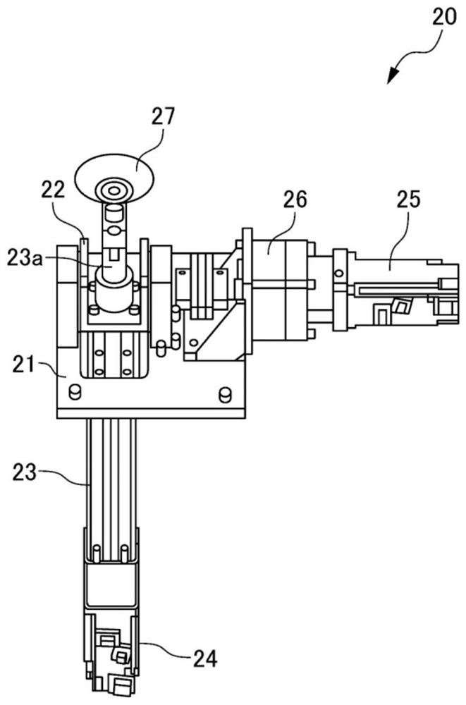
[0072] Figure 10 It is a perspective view which shows the lifter 20B of 2nd Embodiment.

[0073] Figure 11 It is a sectional view which shows the lifter 20B of 2nd Embodiment.

[0074] The second embodiment differs from the first embodiment only in that the lifter 20 in the first embodiment is replaced with a lifter 20B. Therefore, here, only the lifter 20B will be described, and the same reference numerals as those in the first embodiment will be assigned to the same configurations as in the first embodiment, and detailed description will be omitted.

[0075] The lifter 20B of the second embodiment includes a cam member 201 , a support member 202 , a center shaft 203 , a cylinder main body 204 , a direct drive servo motor 205 , and a vacuum cup 206 .

[0076] The cam member 201 is attached to the lower mold 10 or a backing plate that supports the lower mold 10 , and is fixed so as not to move relative to the lower mold 10 . Two cam members 201 are arranged facing each o...


PUM


Abstract

There is provided a die device capable of reliably releasing a workpiece from a die even when the workpiece has an undercut, and conveying the workpiece to a next process. The die device includes a lower die; and a lifter that lifts a pressed workpiece from the lower die. The lower die has an undercut region which is a portion that interferes with the workpiece when the workpiece is moved along a press direction, and the lifter includes a vacuum cup that comes into contact with the workpiece; a rod part having a distal end provided with the vacuum cup; and a linear drive servomotor for causing the rod part to advance / retreat in an axial direction, and further including a rotary drive servomotor that turns the lifter in a direction orthogonal to the axial direction, wherein the lifter moves the workpiece by combining both movement along the press direction and movement in a direction inclined to the press direction.

Description

technical field [0001] The invention relates to a mold arrangement. Background technique [0002] When forming a stamped product, the following operation is performed: Using a cam driver, etc., a movable punch is used to form the workpiece from a direction crossing the mold clamping direction, thereby forming an undercut on the workpiece relative to the mold clamping direction. At this time, the movable mold forming the undercut portion is retracted, and the workpiece is released from the lower mold (for example, Patent Document 1). [0003] Generally, when press forming is used to form automobile body parts, it is formed through multiple processes such as stretch forming, trim forming, bending forming, and piercing forming. In this case, since multiple molds are required, considering combining processes and reducing the installation area of ​​the equipment, it is considered to combine multiple molds, for example, to perform stretch molding, bending molding, and trim moldin...

Claims


Application Information

Patent Timeline
Patent Type & Authority Applications(China)
IPC IPC(8): B21D37/10B21D45/04
CPCB21D37/10B21D45/04B21D53/88B21D22/06B21D45/02B21D19/084B21D37/08
Inventor 坂井裕石井亮金井義男
Owner HONDA MOTOR CO LTD
Why Eureka
Try Eureka