Articulated dump truck

a dump truck and articulation technology, applied in the direction of vehicle springs, towing devices, vehicles, etc., can solve the problems of failure to recognise the significant benefits conferred by such a system, and achieve the effect of improving the ride performance of the vehicle, sufficient resistance to roll movement, and increasing roll complian

Inactive Publication Date: 2010-04-29
TIMONEY EANNA PRONSIAS +1
View PDF21 Cites 34 Cited by
  • Summary
  • Abstract
  • Description
  • Claims
  • Application Information

AI Technical Summary

Benefits of technology

[0017]The invention provides an independent suspension system on the front chassis of an articulated dump truck of the type described herein. Before the present invention there has been no disclosure of this type of dump truck vehicle having in combination with an articulated joint which allows rotation about both vertical and longitudinal axes an independent front suspension system. This may be because of the significant difficulty in packaging a sufficiently robust independent suspension in a dump truck vehicle of this type and the failure to recognise the significant benefits which such a system confers. The fact that the longitudinal bearing in the articulation joint decouples the front and rear chassis frames in roll appears to have lead those versed in the art to discount the utility of providing increased roll compliance in the front suspension in order to improve the ride performance of the vehicle. When such compliance has been provided, relatively stiff springs have been employed to provide sufficient resistance to roll movements induced in cornering. Independent suspension on the other hand maximises the anti-roll moment for a given spring rate measured at the wheel because the springs effectively act at the wheels rather than at the spring location and consequently have a larger effective moment arm. The invention minimises lateral vibration of the cab and thus allows a driver to comfortably operate at higher speeds over rough ground with consequent increase in productivity. The modular design disclosed herein enables the invention to be carried out in a particularly robust and affordable manner.

Problems solved by technology

This may be because of the significant difficulty in packaging a sufficiently robust independent suspension in a dump truck vehicle of this type and the failure to recognise the significant benefits which such a system confers.

Method used


Image

  • Articulated dump truck
  • Articulated dump truck
  • Articulated dump truck

Examples


Embodiment Construction

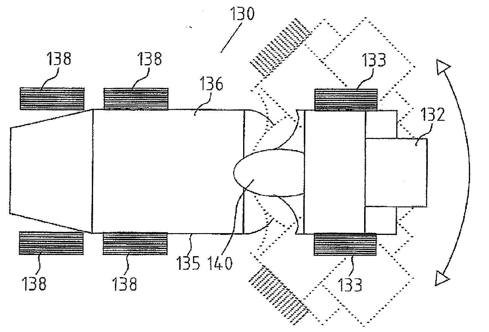
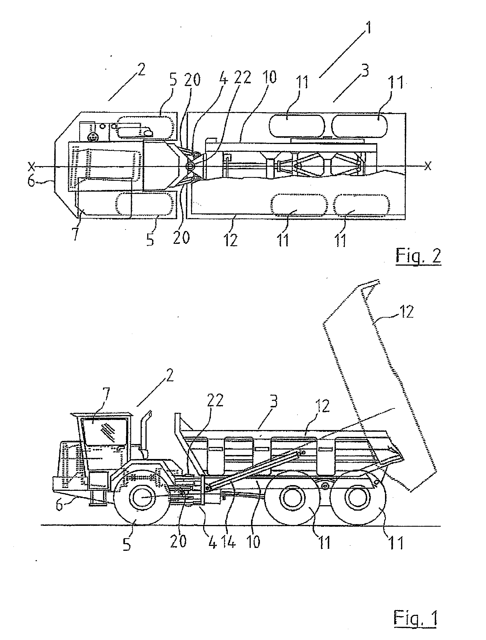
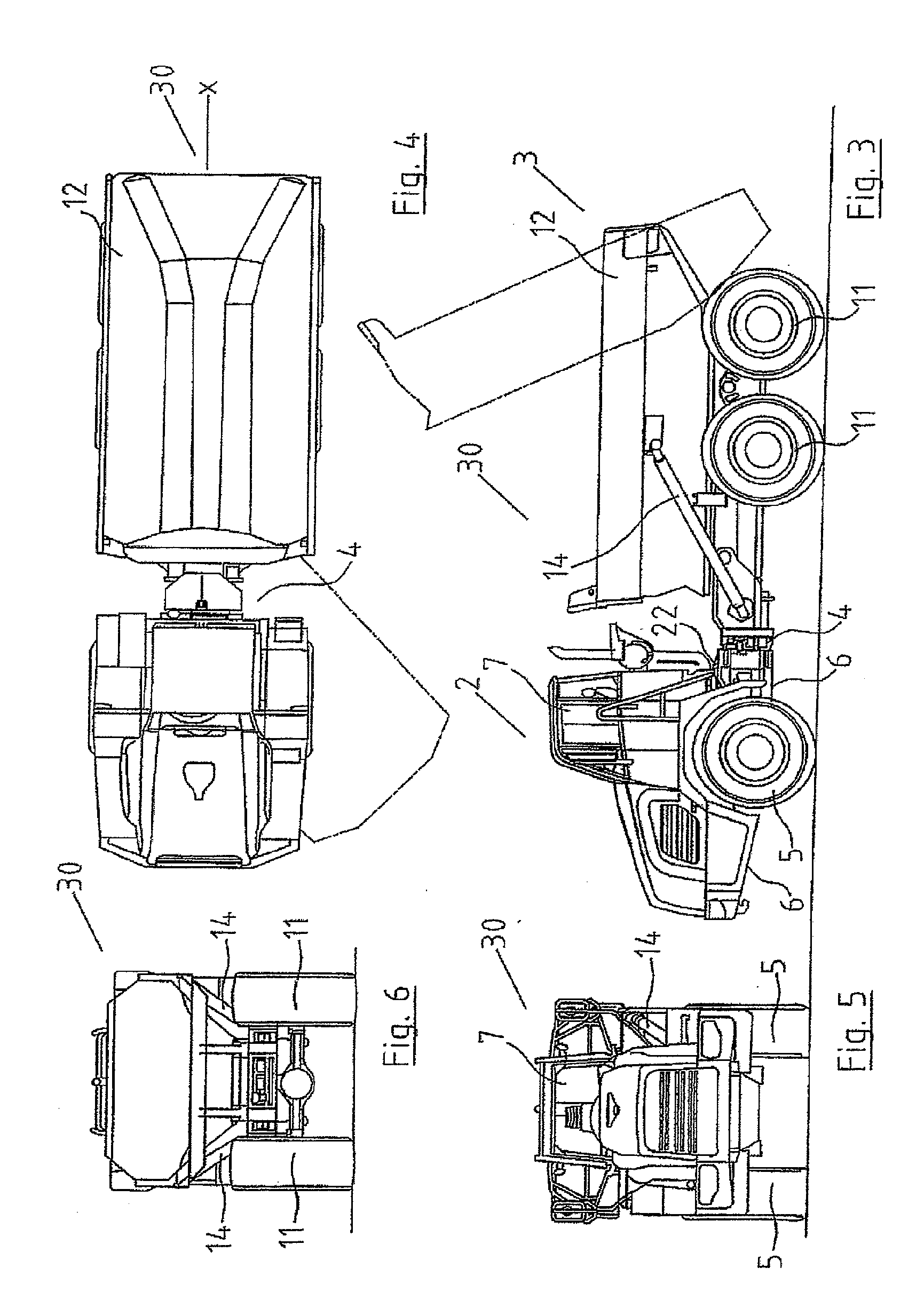
[0067]Referring to the drawings, and initially to FIGS. 1 and 2 thereof, there is illustrated an articulated dump truck vehicle according to the invention indicated generally by the reference numeral 1. The articulated dump truck 1 includes a front tractor unit 2 connected to an associated rear trailer unit 3 by an articulated coupling 4. The front tractor unit 2 is provided with an independent suspension system for mounting wheels 5 on a front chassis 6 of the front tractor unit 2.

[0068]The front tractor unit 2 has a cab 7 within which are located controls for driving and operation of the articulated dump truck 1.

[0069]The rear trailer unit 3 has a rear chassis 10 mounted on two pairs of wheels 11. A tipping container 12 is pivotaly mounted on the rear chassis 10 on which it can be tipped as shown in broken outline in FIG. 1 by means of rams 14 at each side.

[0070]The articulated coupling 4 can rotate about longitudinal axis X and vertical axis 22 of the truck 1 but is unable to rot...


PUM


Abstract

An article dump truck has a front tractor unit connected to an associated rear trailer unit with a tipping container by an articulated coupling. The articulated coupling is operable to allow the front tractor unit and rear trailer unit to pivot about a vertical pivot axis, rams being provided to turn the front tractor unit and rear trailer unit about the pivot to steer the dump truck. The articulated coupling also allows the front tracter unit and rear trailer unit to rotate relative to each other about a longitudinal axis of the dump truck. In addition, the front tractor unit has a front chassis mounted on a pair of wheels by an independent suspension system.

Description

[0001]This application is a Continuation of U.S. application Ser. No. 10 / 574,270, filed on Mar. 1, 2006, which claims the priority benefit of Ireland Application Nos. S2003 / 0720 and S2003 / 0721, filed on Oct. 1, 2003, which is hereby incorporated by reference as if fully set forth herein.BACKGROUND OF THE INVENTION[0002]This invention relates to an articulated dump truck (ADT) which consists of two vehicle chassis frames mounted on wheels and linked by a steerable articulation joint, with a tipping load container mounted pivotally on the rear chassis while the front chassis carries the cab and prime mover. The articulation joint allows rotation around two axes, namely a first vertical axis and a second longitudinal axis. The rear chassis is mounted on four wheels, two wheels being displaced longitudinally on each side, while the front chassis is mounted on two wheels.[0003]The vehicle is steered by controlling the relative rotation of the chassis frames around the vertical axis at th...

Claims


Application Information

Patent Timeline
Patent Type & Authority Applications(United States)
IPC IPC(8): B62D53/00B60G21/055B60G3/20B60G7/02B60G11/16B60P1/28B62D12/00B62D53/02B65F3/20
CPCB60G3/20B62D53/021B60G11/16B60G2200/144B60G2200/422B60G2202/12B60G2204/124B60G2204/1244B60G2204/143B60G2204/15B60G2204/19B60G2206/0114B60G2206/124B60G2206/60B60G2300/026B60G2300/07B62D12/00B60G7/02
Inventor TIMONEY, EANNA PRONSIASTIMONEY, SEAN
Owner TIMONEY EANNA PRONSIAS
Why Eureka
Try Eureka