Fluid ejection device

a fluid ejection and fluid technology, applied in the direction of printing, other printing apparatus, etc., can solve the problems of power consumption, upsizing of the device, difficulty in generating accurate driving voltage waveform, etc., to avoid the possibility of the flow of electric energy to the power source side, reduce power consumption, and ensure the effect of reliable electric energy regeneration

Active Publication Date: 2010-04-29
SEIKO EPSON CORP
View PDF4 Cites 24 Cited by
  • Summary
  • Abstract
  • Description
  • Claims
  • Application Information

AI Technical Summary

Benefits of technology

[0023]Also, when regenerating the electric energy of the driving element, limitation of interchange of the electric power between the electric storage unit and the power source may be provided. For example, a configuration in which the electric storage unit and the power source are connected with a diode so as to prevent the electric current from flowing from the electric storage unit side to the power source side is also applicable. In this configuration, the probability of flow of the electric energy regenerated from the driving element to the power source side can be avoided, so that regeneration of the electric energy in the electric storage unit is ensured. A configuration in which the switch is provided between the electric storage unit and the power source and the switch is disconnected when regenerating the electric energy is also applicable. In this configuration as well, the probability of the flow of the electric energy to the power source side can be avoided, so that reliable regeneration of the electric energy to restrain the power consumption is achieved.

Problems solved by technology

When an amplifier element such as a transistor for generating the driving voltage waveform, there arise problems such as power consumption due to dissipation in the amplifier element (for example, collector dissipation of the transistor) or upsizing of the device due to the necessity of a heat discharging panel for releasing heat generated by the power consumption.
However, with the proposed technique, although high power efficiency is achieved, there is a problem of difficulty in generating an accurate driving voltage waveform.
In other words, since the power efficiency is enhanced by switching the power sources, the generated driving voltage waveform assumes a stepped waveform in which the voltage is changed in a staircase pattern, so that output of an accurate waveform is difficult.
However, when the driving voltage waveform is generated using the amplifier element such as the transistor, the electric power is consumed by the amplifier element, and hence the power efficiency is lowered.
Also, when regenerating the electric energy of the driving element, limitation of interchange of the electric power between the electric storage unit and the power source may be provided.

Method used


Image

  • Fluid ejection device
  • Fluid ejection device
  • Fluid ejection device

Examples


first modification

D-1. First Modification

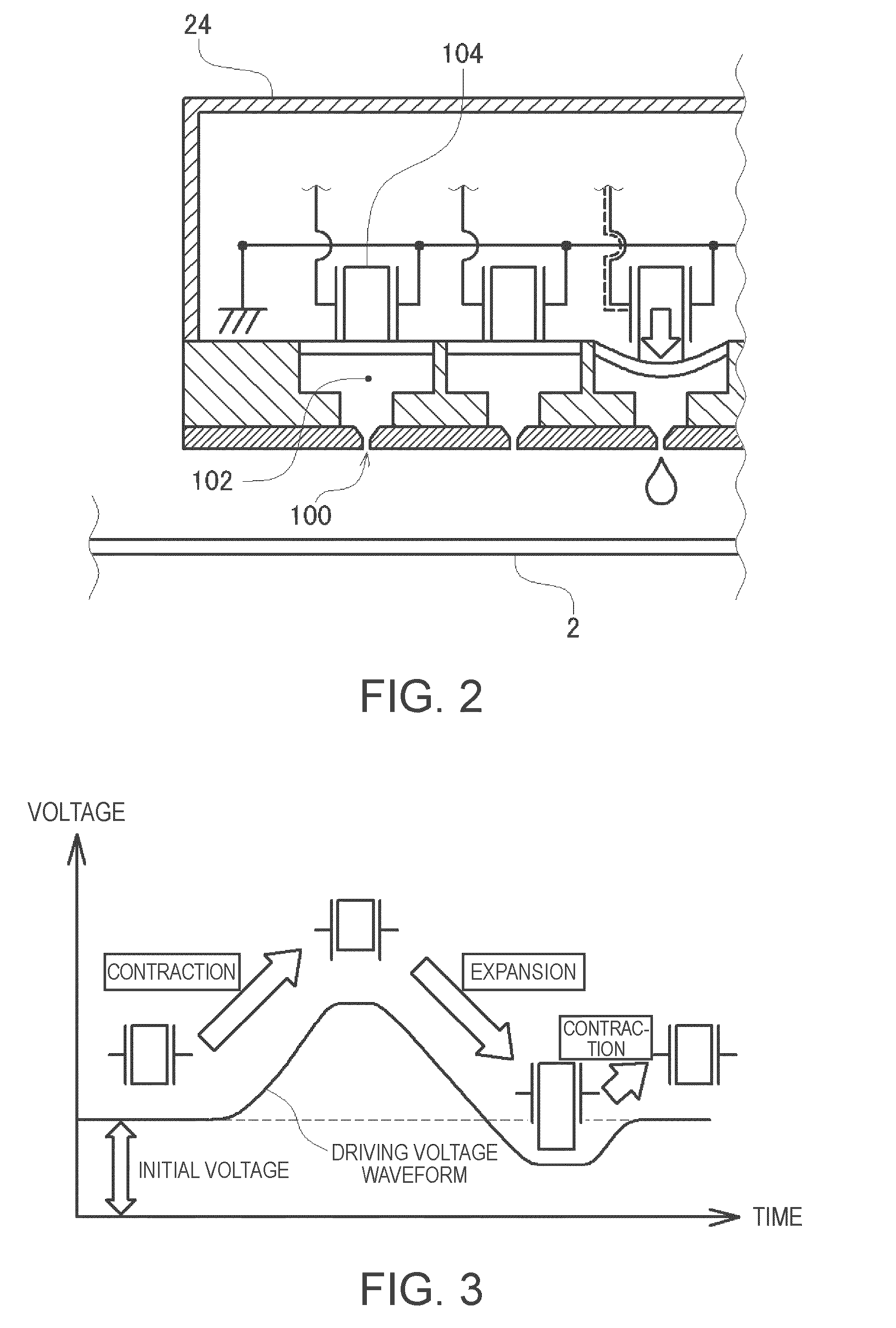
[0088]In the description of the embodiment described above, the voltage of the power source unit is set when outputting the driving voltage waveform for ejecting the ink drops. However, the driving voltage waveform generating circuit in this embodiment can be applied effectively to a case other than generating the driving voltage waveform. For example, in the inkjet printer 10 in the embodiment described above, the constant initial voltage is applied to the piezoelectric elements also while the ink drops are not ejected (see FIG. 3). Therefore, in the driving voltage waveform generating circuit in this embodiment, the following advantages are achieved by setting the voltage of the power source unit when applying the initial voltage.

[0089]FIG. 10 is an explanatory drawing showing a state in which the voltage of the power source unit is set when applying the initial voltage to the piezoelectric element. As illustrated, when applying the initial voltage from a st...

second modification

D-2. Second Modification

[0092]In the description of the embodiment described above, the voltage of the power source unit is changed according to the driving voltage waveform to be generated. However, the voltage may be changed for correcting the individual specificity among the piezoelectric elements or the ejection nozzles instead of changing according to the driving voltage waveform. For example, from the reasons such as variations in quality at the time of manufacture, the piezoelectric elements may include those being deformed by an extent smaller than other piezoelectric elements when the voltage is applied. In such a case, by changing the voltage of the power source unit and applying the larger voltage, the individual difference can be corrected to cause the piezoelectric elements to be deformed by an accurate extent and, consequently, the ink drops can be ejected accurately.

third modification

D-3. Third Modification

[0093]In the driving voltage waveform generating circuit according to this embodiment, the power consumption can further be restrained by connecting the capacitors to the respective output terminals of the power source unit.

[0094]FIG. 11 is an explanatory drawing showing the driving voltage waveform generating circuit according to the modification in which the capacitor is connected to the output terminal of the power source unit. As illustrated, capacitors C1 to C7 are connected respectively to the output terminals of the power source unit202. Also, switches are provided between the capacitors and the power source unit 202 (switch indicated as “A” in the drawing), so that the power source and the capacitors can be disconnected. With the circuit configuration as described above, the charge applied to the piezoelectric elements can be regenerated by the capacitor and, consequently, the power consumption can further be restrained. This point will be described wi...


PUM


Abstract

A fluid ejection device configured to eject fluid from an ejection port includes a driving element that pressurizes the fluid and causes it to be ejected from the ejection port by being driven according to a voltage applied thereto. A driving voltage waveform selecting unit selects a driving voltage waveform to be applied to the driving element from among a plurality of types of the stored driving voltage waveforms. Power sources set the voltage to be outputted. A power source voltage determining unit determines voltages to be set to the power sources on the basis of the selected driving voltage waveform. A driving voltage waveform applying unit applies the selected driving voltage waveform to the driving element by setting the determined voltages to the power sources and connecting the power sources to the driving element while switching the same.

Description

[0001]This application claims priority to Japanese Patent Application No. 2008-275232 filed on Oct. 27, 2008, and the entire disclosure thereof is incorporated herein by reference.BACKGROUND[0002]1. Technical Field[0003]The present invention relates to a technique to eject fluid from an ejection head.[0004]2. Related Art[0005]An inkjet printer configured to print an image by ejecting ink on a printing medium is now widely used as an image output apparatus because printing of high-quality images is easily achieved. Also, by ejecting various type of fluid prepared to have adequate components (for example, liquid including fine particles of functional materials dispersed therein or semifluid such as gel) instead of the ink on a substrate using this technique, manufacturing of various types of precision components such as electrodes, sensors, and biochips is considered to be easily achieved.[0006]In the technique as described above, a specific ejection head provided with fine ejection p...

Claims


Application Information

Patent Timeline
Patent Type & Authority Applications(United States)
IPC IPC(8): B41J29/38
CPCB41J2/04548B41J2/04573B41J2/0459B41J2/04588B41J2/04581
Inventor TABATA, KUNIOAZAMI, NOBUAKIYOSHINO, HIROYUKIMIYAZAKI, SHINICHIOSHIMA, ATSUSHIIDE, NORITAKA
Owner SEIKO EPSON CORP
Why Eureka
Try Eureka