
Photographing control device, microscope and program

a control device and microscope technology, applied in closed circuit television systems, instruments, television systems, etc., can solve the problems of critical loss of time generated by time lapse photography experiments, extended time-lapse photography experiments, etc., and achieve the effect of easy confirmation

Active Publication Date: 2010-04-29
NIKON CORP
View PDF12 Cites 9 Cited by
  • Summary
  • Abstract
  • Description
  • Claims
  • Application Information

AI Technical Summary

Benefits of technology

[0004]With the foregoing in view, it is an object of the present invention to easily confirm whether time lapse photography is being executed normally or not.
[0009]According to the first or second aspect, the monitoring result of the operation of time lapse photography can be displayed. Particularly, according to the first or second aspect of the present invention, it can be easily confirmed whether time lapse photography is being executed normally.

Problems solved by technology

The time lapse photography experiment, however, extends over a long period of time (e.g. several hours).
If the experiment must be started over again due to an incorrect procedure of the experiment, due to an apparatus not operating normally or due to the shift of the photographing position, the loss of time that this error generates is critical.

Method used


Image

  • Photographing control device, microscope and program
  • Photographing control device, microscope and program
  • Photographing control device, microscope and program

Examples


Embodiment Construction

[0057]Embodiments of the present invention will now be described with reference to the drawings.

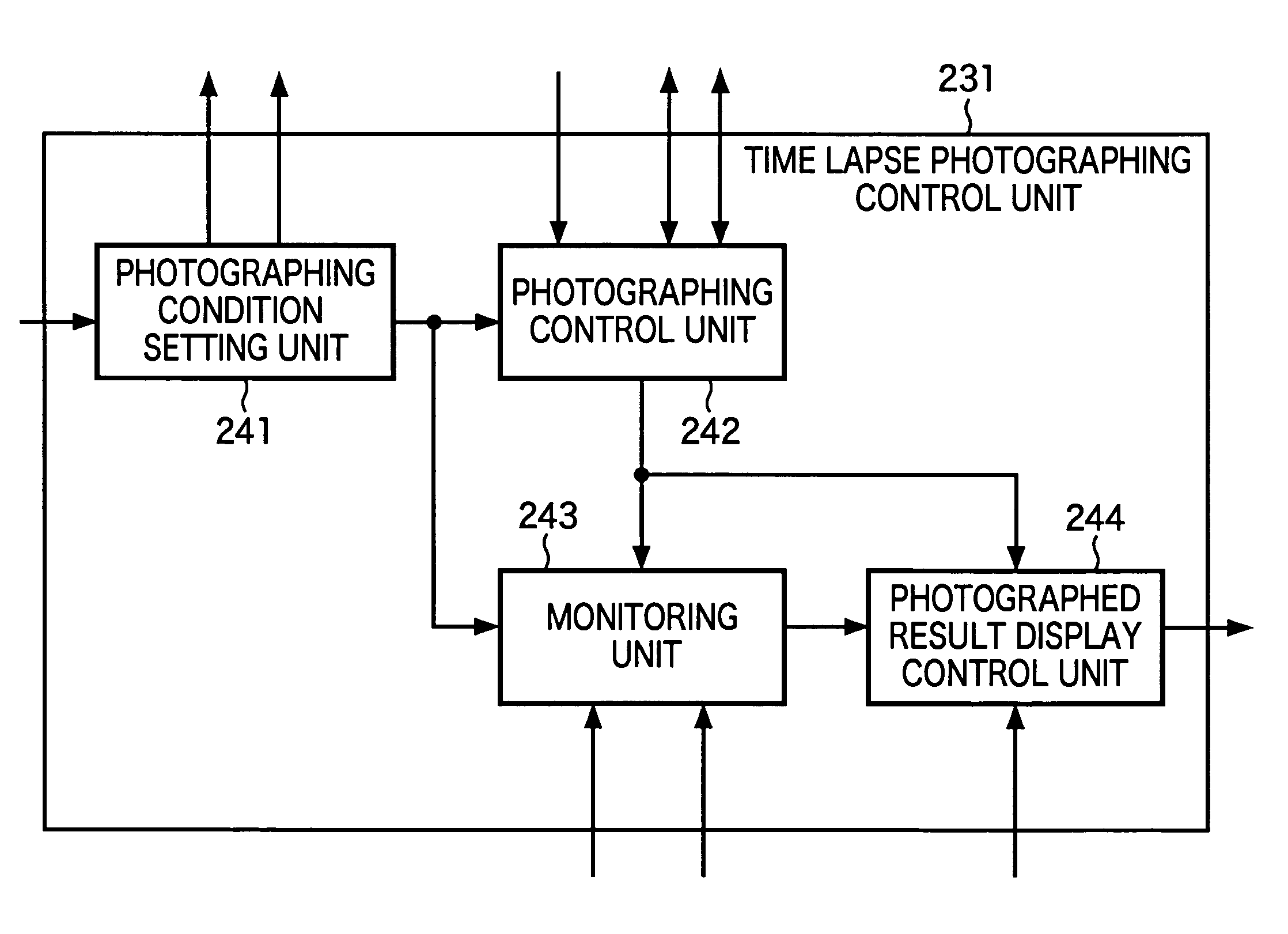
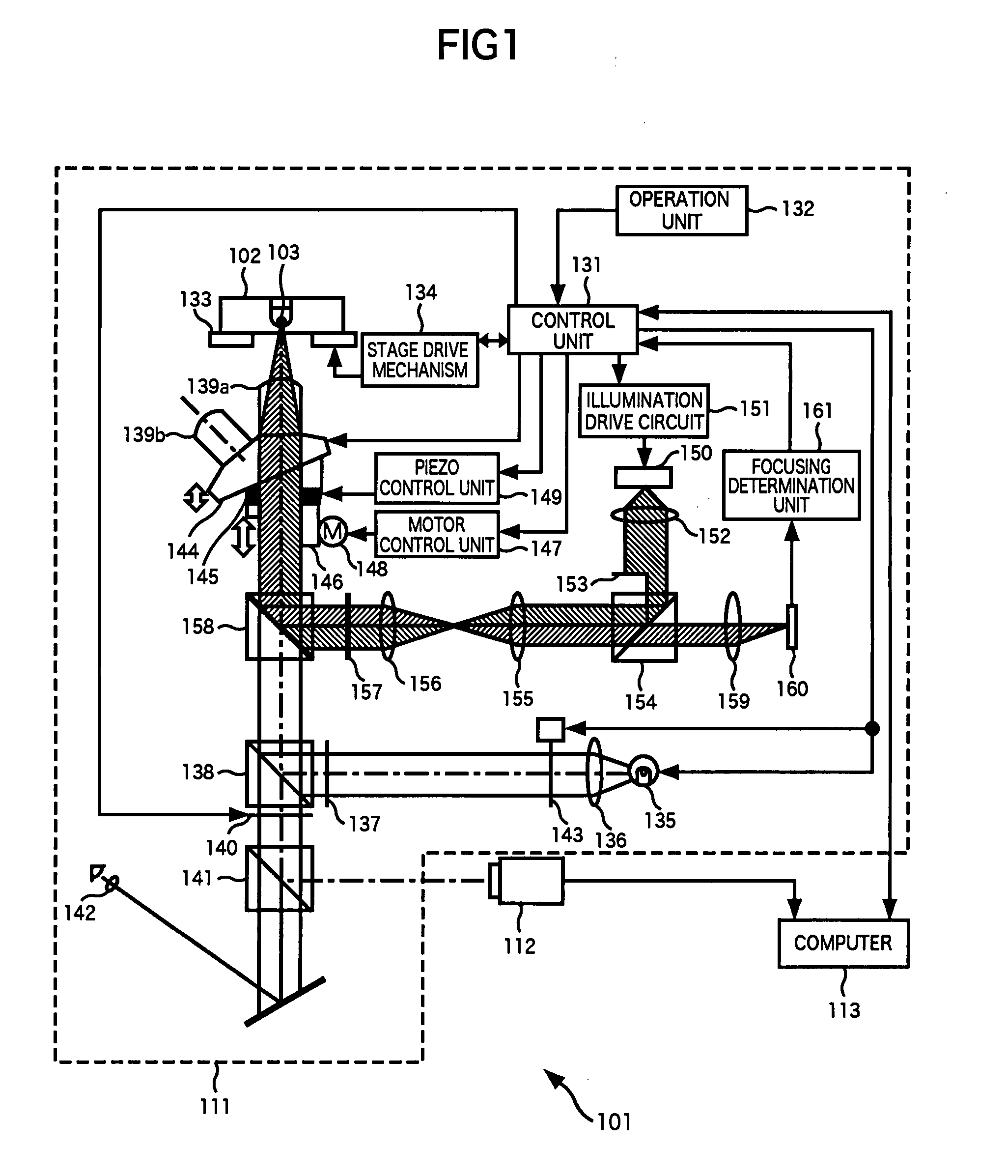
[0058]FIG. 1 is a block diagram depicting an embodiment of a time lapse photography experiment system to which the present invention is applied. The time lapse photography experiment system 101 in FIG. 1 is a system to perform a time lapse photography experiment on a sample 103, which is a test object, soaked in a solution of each well of a well plate 102 that is installed on an electric stage 133 of an inverted microscope 111, for example. In FIG. 1, only one well is shown on the well plate 102, this for convenience, but in reality a plurality (e.g. 96) of wells are disposed on the well plate 102, and a sample is disposed in each well according to necessity.

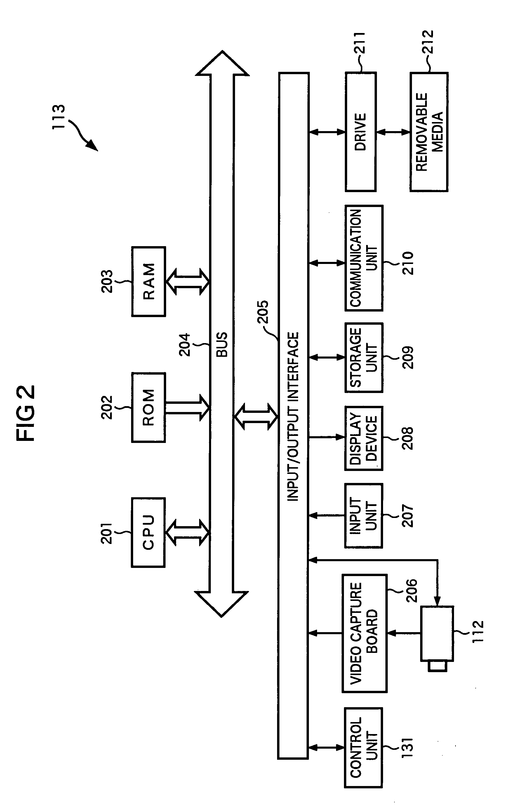
[0059]The time lapse photography experiment system 101 is constituted by the inverted microscope 111, a camera 112 and a computer 113. The computer 113 is connected to a control unit 131 of the inverted microscope 111 and the camera 1...


PUM


Abstract

The present invention relates to a photographing control device, microscope and program that can simply confirm whether time lapse photography is being executed normally or not.A number of a display target round, time required for processing of the round, and the operation state of each device of an inverted microscope and a camera in the round, are displayed in a window 431 on a photographed result display screen 421 that displays the photographed result of the time lapse photography. The individual operation time of the each device of the inverted microscope and the camera from the start of the processing of a photographing point selected in a list box 433 to the completion of the photographing of a channel selected in a list box 434, is displayed in a window 435. When an image button is pressed, the image of a photographed sample is displayed. The present invention can be applied to software for controlling time lapse photography using a microscope, for example.

Description

TECHNICAL FIELD[0001]The present invention relates to a photographing control device, microscope and program, and more particularly to a photographing control device, microscope and program that allow to easily check the state of a time lapse photography operation.BACKGROUND ART[0002]One experiment method for observing a sample using a microscope is photographing microscopic images at a predetermined interval (hereafter referred to as “time lapse photography”), reproducing a series of photographed images after photographing completes, and observing the change of the state of the sample in a time series as a moving image (hereafter referred to as “time lapse photography experiment”) (e.g. see Patent Document 1). The time lapse photography experiment method is extremely effective as an experiment method to observe the change of a live cell in a time series, for example.[Patent Document 1] Japanese Patent Application Laid-Open No. 2002-277754[0003]The time lapse photography experiment,...

Claims


Application Information

Patent Timeline
IPC IPC(8): H04N7/18H04N5/232
CPCG02B21/0088G02B21/367H04N5/2352H04N5/23245H04N5/23293H04N5/232G02B21/245H04N23/667H04N23/633H04N23/72
Inventor OKAMOTO, TAKAAKI
Owner NIKON CORP
Learn More