Projector and projector control method

a projector and control method technology, applied in the field of projectors, can solve problems such as a lot of trouble, and achieve the effect of improving user-friendliness

Active Publication Date: 2010-04-29
SEIKO EPSON CORP
View PDF38 Cites 52 Cited by
  • Summary
  • Abstract
  • Description
  • Claims
  • Application Information

AI Technical Summary

Benefits of technology

[0010]An advantage of some aspects of the invention is to provide a technology which improves user-friendliness.

Problems solved by technology

In the event that the user is not aware of the keystone automatic correction function, as the user implements the keystone manual correction while observing the image bounds of the image projected onto the screen in the way heretofore described, it takes a lot of trouble, and it takes time until an image whose image bounds form a rectangle is displayed on the screen, causing inconvenience.
This kind of problem has been a problem common not only to a case of implementing a keystone correction in the projector, but also to a case of adjusting a projected image in accordance with a relative positional relationship between the projector and the projection surface in a case of adjusting a focus, in a case of carrying out an enlargement and reduction (zoom) adjustment, or the like.

Method used


Image

  • Projector and projector control method
  • Projector and projector control method
  • Projector and projector control method

Examples


second embodiment

B. Second Embodiment

B-1. Configuration of Embodiment

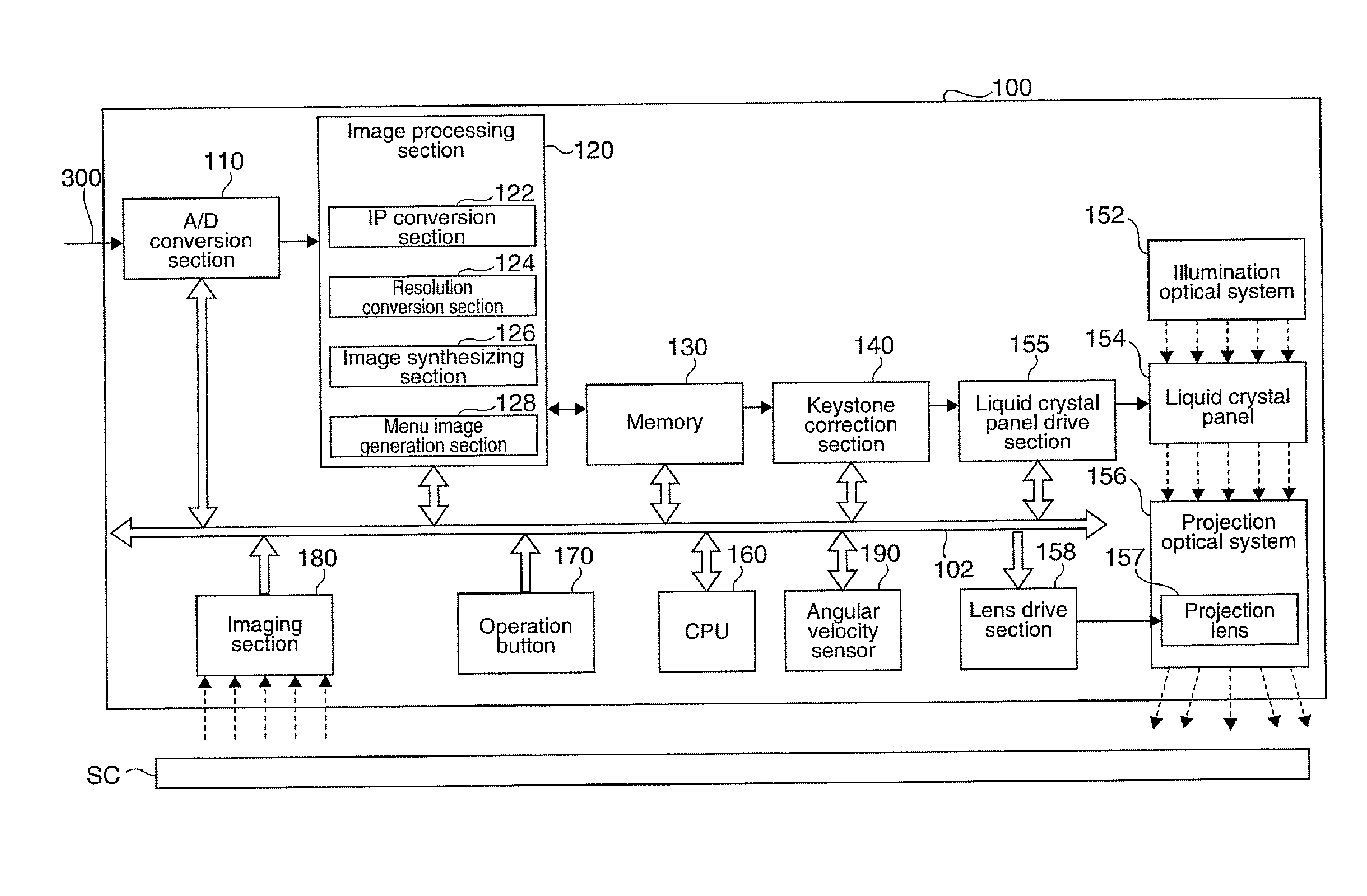
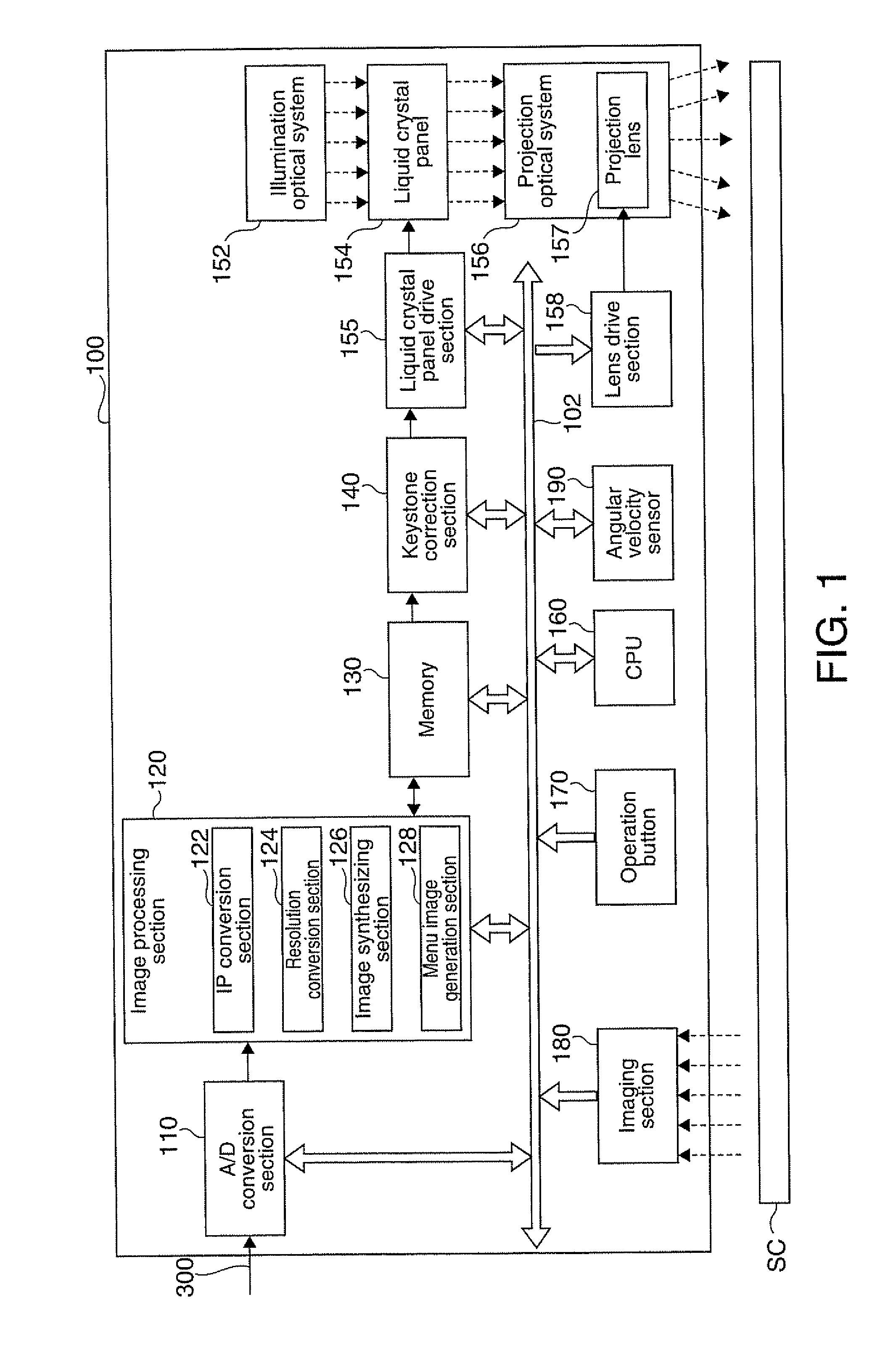
[0088]FIG. 6 is a block diagram schematically showing a configuration of a projector as the second embodiment of the invention. The projector 100A in this embodiment and the projector 100 of the first embodiment have same structure except only following points, that is, in this embodiment, a guide pattern data (stated later) is stored in the memory 130, and the control program executed on the CPU 160 is different from the first embodiment.

light modulator

[0089]The CPU 160 in the projector 100A of this embodiment is, based on the angular velocity detected by the angular velocity sensor 190, not only causing an automatic keystone correction process to be started but also causing a keystone correction process in the keystone correction section 140 to be cancelled. Also, the CPU 160 causes the keystone correction section 140 to cancel the keystone correction process, and also to output guide pattern data GD stored in advance in the memo...

modification examples

C. Modification Examples

[0120]The invention, not being limited to the heretofore described embodiments, can be implemented in various forms without departing from the scope thereof.

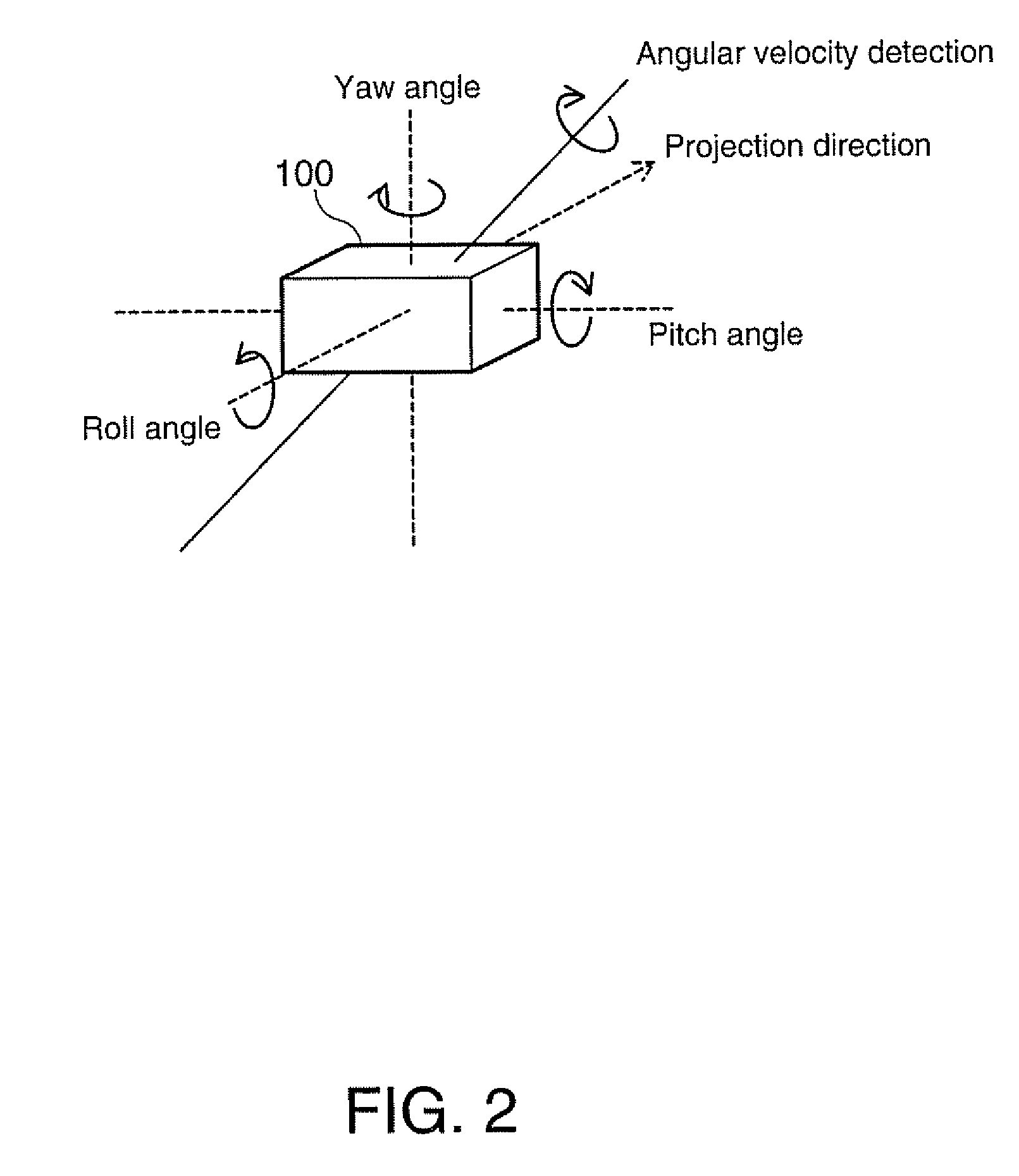
[0121]1. In the heretofore described embodiments, the angular velocity sensor 190 is used to detect a movement and stop of the projector 100 but, not being limited to the angular velocity sensor 190, it is sufficient to use one which can detect a movement and stop of the projector 100. It is possible to use, for example, a G sensor, an acceleration sensor, or an optical sensor, in place of the angular velocity sensor 190. Also, it is also possible to detect a movement and stop of the projector 100 based on an image imaged by the imaging section 180.

[0122]2. In the heretofore described embodiments, the distance detection pattern is projected onto the screen SC, and a keystone correction amount and a position of the focus lens are calculated based on the image imaged by the imaging section 180, but a method...


PUM


Abstract

A projector which projects an image onto a projection surface, and displays it thereon, includes: a light source; a light modulator which modulates light from the light source into an image light representing the image; a projection optical system which projects the image light modulated by the light modulator onto the projection surface; a keystone distortion correction section which carries out a keystone distortion correction process for correcting a keystone distortion of the image projected onto the projection surface; a detection section which detects a stop of a movement of the projector; and a control section which, on the stop of the movement of the projector being detected in the detection section, causes the keystone distortion correction section to start the keystone distortion correction process in accordance with a relative positional relationship between the projector after being moved and the projection surface.

Description

[0001]The entire disclosure of Japanese Patent No. 2008-278551 filed Oct. 29, 2008, Japanese Patent No. 2008-278558 filed Oct. 29, 2008 and Japanese Patent No. 2009-185002 filed Aug. 8, 2009 are expressly incorporated by reference herein.BACKGROUND[0002]1. Technical Field[0003]The present invention relates to a projector which displays an image on a projection surface.[0004]2. Related Art[0005]When a projector is used to cause an image whose image bounds form a rectangle to be displayed on a projection surface of a screen or the like, depending on a relative positional relationship between the projector and the projection surface, it may happen that the image bounds of the image displayed on the projection surface (hereafter referred to also as the “projection image”) are distorted into a trapezoid. In this kind of case, a keystone correction is used which corrects a distortion of the projection image (hereafter referred to also as a “keystone distortion”).[0006]Heretofore, in the p...

Claims


Application Information

Patent Timeline
Patent Type & Authority Applications(United States)
IPC IPC(8): G03B21/14G03B3/00
CPCH04N9/3185G03B21/14H04N9/3197H04N9/3194
Inventor KUBOTA, SHINJI
Owner SEIKO EPSON CORP
Why Eureka
Try Eureka