System and method for emulating an ideal diode in a power control device

a power control device and ideal diode technology, applied in the field of system and method for controlling a transistor to emulate an ideal diode, can solve the problems of substantial loss due to diode power dissipation, inefficient conventional diodes, and substantial actual voltage drop and consequent power dissipation across conventional diodes used in power conversion systems

Active Publication Date: 2010-04-29
LEACH INT
View PDF22 Cites 11 Cited by
  • Summary
  • Abstract
  • Description
  • Claims
  • Application Information

AI Technical Summary

Benefits of technology

[0005]Aspects of the invention relate to a system and method for emulating an ideal diode for use in a power control device. In one embodiment, the invention relates to a circuit for emulating an ideal diode, the circuit including at least one field effect transistor including a source, a drain, a gate, and a body diode, and a comparator including a first input coupled to the source, a second input coupled to the drain, and an output coupled to the gate, wherein the comparator is configured to activate the at least one field effect transistor based on whether the voltage at the source is greater than the voltage at the drain, and wherein the body diode comprises an anode coupled to the source and a cathode coupled to the drain.
[0006]In another embodiment, the invention relates to a circuit for emulating an ideal diode, the circuit including at least one field effect transistor including a source, a drain, a gate, and a body diode, an input, an output coupled to the drain, a control circuit including a current sensor coupled between the input and the source, and a control circuit output coupled to the gate, wherein the control circuit is configured to activate the at least one field effect transistor based on whether the current flowing into the source is greater than a predetermined threshold, and wherein the body diode comprises an anode coupled to the source and a cathode coupled to the drain.
[0007]In yet another embodiment, the invention relates to a power system including a transformer rectification unit, the power system including an alternating current power source coupled to the transformer rectification unit, a direct current load coupled to the transformer rectification unit, the transformer rectification unit including a primary winding, a secondary winding in electromagnetic communication with the primary winding, and at least one ideal diode circuit coupled to the secondary winding, the at least one ideal diode circuit including at least one field effect transistor coupled to a control circuit.

Problems solved by technology

However, power conversion systems typically include high frequency conversion and losses due to diode power dissipation can therefore become substantial.
In such case, conventional diodes can be inefficient as compared to diodes having approximately ideal characteristics (e.g., negligible voltage drop).
The actual voltage drop and consequent power dissipation across conventional diodes used in power conversion systems can be substantial under high current conditions.
Such large scale power dissipation can adversely affect the reliability of electronics used within or in conjunction with the power conversion system.

Method used


Image

  • System and method for emulating an ideal diode in a power control device
  • System and method for emulating an ideal diode in a power control device
  • System and method for emulating an ideal diode in a power control device

Examples


Embodiment Construction

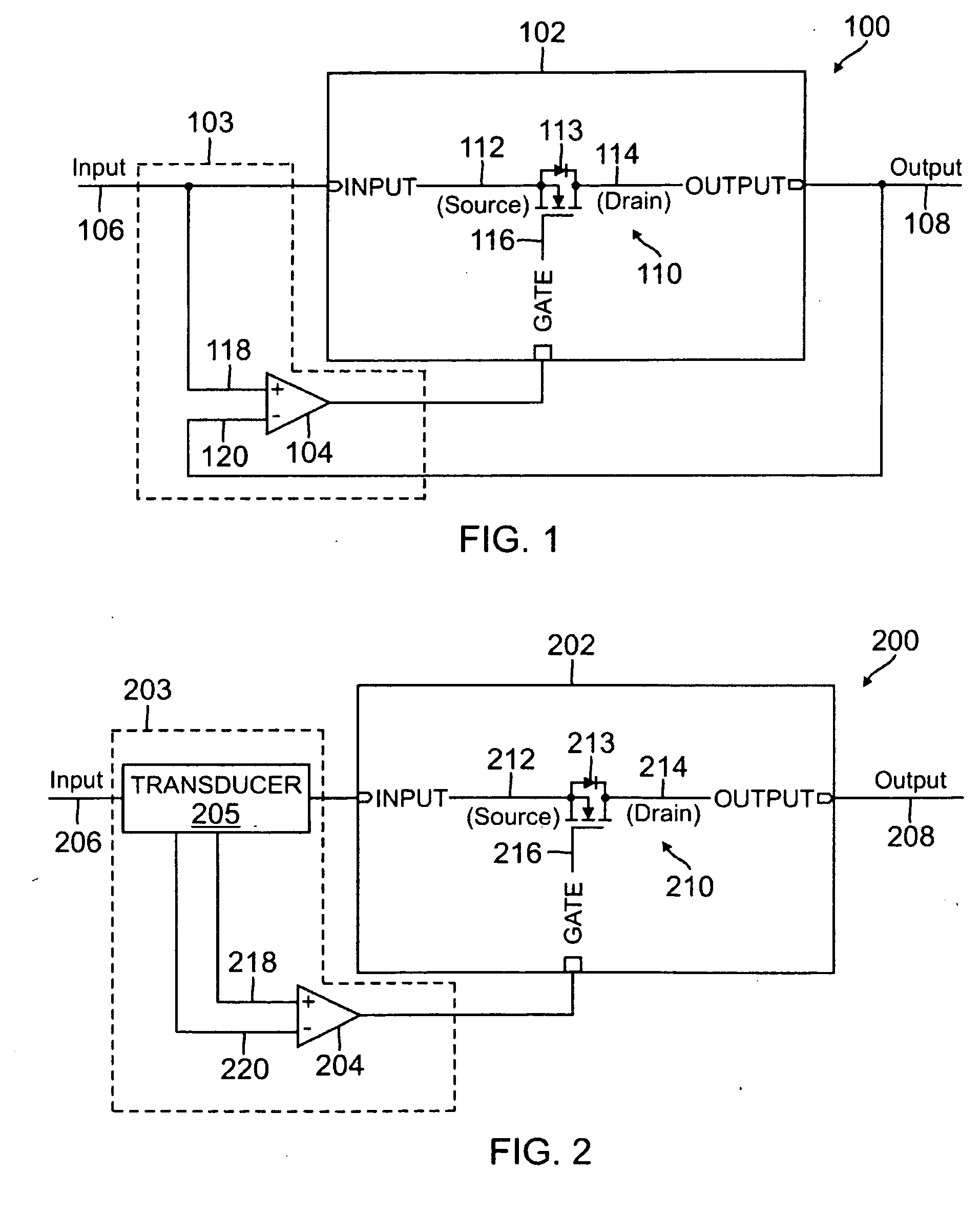
[0014]Embodiments of ideal diode circuits include transistors coupled to control circuits. The transistors are configured to operate as a diode or unidirectional switch having characteristics approximating a theoretical ideal diode. The control circuits can detect current flow into the ideal diode circuit. Based on the detected current, the control circuits can activate (turn on) or deactivate (turn off) the transistors. Activation of the transistors minimizes the voltage drop across the ideal diode circuit, while deactivation of the transistors effectively prevents current flow in a reverse direction.

[0015]In one embodiment, the transistor is a field effect transistor (FET) and the control circuit measures voltage at both the source and drain of the FET. In such case, if the voltage at the source is higher than the voltage at the drain by a predetermined threshold, the control circuit can activate the FET to enable minimal voltage drop across the ideal diode circuit. Alternatively,...


PUM


Abstract

A system and method for emulating an ideal diode for use in a power control device is provided. In one embodiment, the invention relates to a circuit for emulating an ideal diode, the circuit including at least one field effect transistor including a source, a drain, a gate, and a body diode, an input; an output coupled to the drain, a control circuit including a current sensor coupled between the input and the source, and a control circuit output coupled to the gate, wherein the control circuit is configured to activate the at least one field effect transistor based on whether the current flowing into the source is greater than a predetermined threshold, and wherein the body diode comprises an anode coupled to the source and a cathode coupled to the drain.

Description

BACKGROUND OF THE INVENTION[0001]The present invention relates to a system and method for emulating an ideal diode for use in a power control device. More specifically, the present invention relates to a system and method for controlling a transistor to emulate an ideal diode.[0002]Conventional diodes are used in any number of applications, and, more specifically, in applications involving rectification. For example, diodes are often used in power conversion systems to convert alternating current into direct current, for over voltage protection, and for blocking reverse currents in systems having multiple power sources (e.g., an uninterruptible power source). The voltage drop across a conventional diode and corresponding power dissipation are generally thought of as being relatively small values. However, power conversion systems typically include high frequency conversion and losses due to diode power dissipation can therefore become substantial. In such case, conventional diodes c...

Claims


Application Information

Patent Timeline
Patent Type & Authority Applications(United States)
IPC IPC(8): H02M7/217H03H11/00
CPCH02M7/217H03K2017/307H03K17/302H03H11/46
Inventor TOFIGH, FARSHIDKRUPPA, OTMAR
Owner LEACH INT
Why Eureka
Try Eureka