
Optical disk device

Active Publication Date: 2010-04-29
HITACHI-LG DATA STORAGE
View PDF4 Cites 0 Cited by
  • Summary
  • Abstract
  • Description
  • Claims
  • Application Information

AI Technical Summary

Benefits of technology

[0005]As described above, in the conventional optical disk device, the wind noise which is generated by the rotating disk leaks easily to the outside of the optical disk device. Particularly, in a so-called slim drive having a thickness of 12.7 or 9.5 millimeters, the disk housed therein reaches a wing portion having a thinner thickness than that of a body portion. Therefore, there is a short distance between the rotating disk and a bottom case and the wind noise which is generated by the rotation of the disk leaks easily to an outside of a housing.
[0006]In the above-mentioned slim drive, the wing portion is provided with an engaging portion which engages the bottom case and a top case with each other. The engaging portion of the top case is provided with a hole for engaging a hook. This engaging portion is provided at a position which is close to the disk, and hence the wind noise leaks easily through the hole of the engaging portion. Therefore, there is a need for reducing the leakage of the wind noise through this engaging portion.
[0007]In addition, in JP2003-36664A mentioned above, the covering member which prevents the leakage of the wind noise is provided as a separate member, and hence a cost of the optical disk device increases for improvement of sound insulation properties. Thus, there is a need for preventing the leakage of the wind noise through the case without using the separate member.
[0008]This invention has been made for providing an optical disk device which is capable of reducing wind noise which leaks through a housing without increasing a cost.
[0010]According to an aspect of this invention, it is possible to reduce the wind noise which leaks through the housing without increasing a manufacturing cost of the housing.

Problems solved by technology

As described above, in the conventional optical disk device, the wind noise which is generated by the rotating disk leaks easily to the outside of the optical disk device.
Therefore, there is a short distance between the rotating disk and a bottom case and the wind noise which is generated by the rotation of the disk leaks easily to an outside of a housing.
In addition, in JP2003-36664A mentioned above, the covering member which prevents the leakage of the wind noise is provided as a separate member, and hence a cost of the optical disk device increases for improvement of sound insulation properties.

Method used


Image

  • Optical disk device
  • Optical disk device
  • Optical disk device

Examples


Embodiment Construction

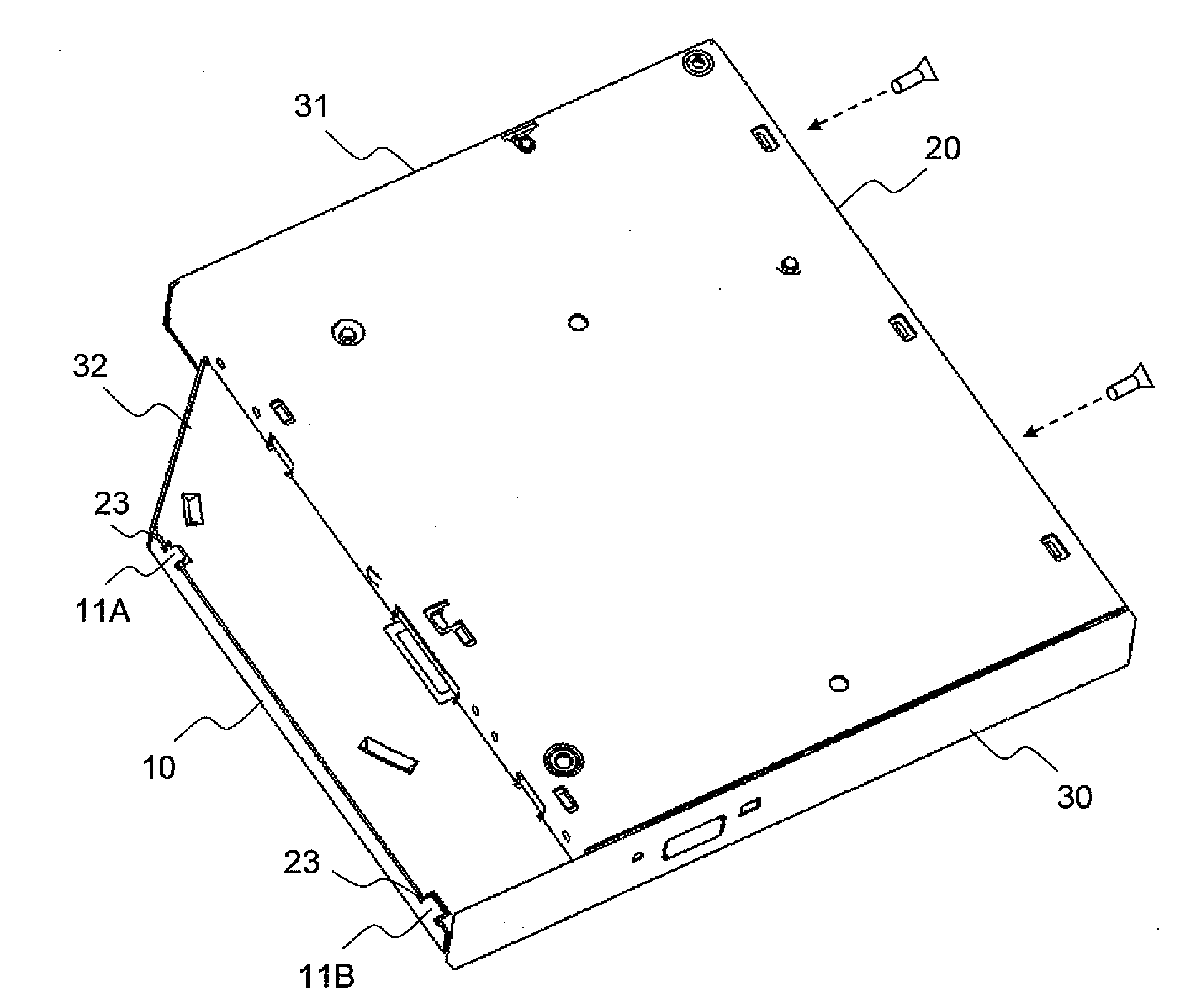
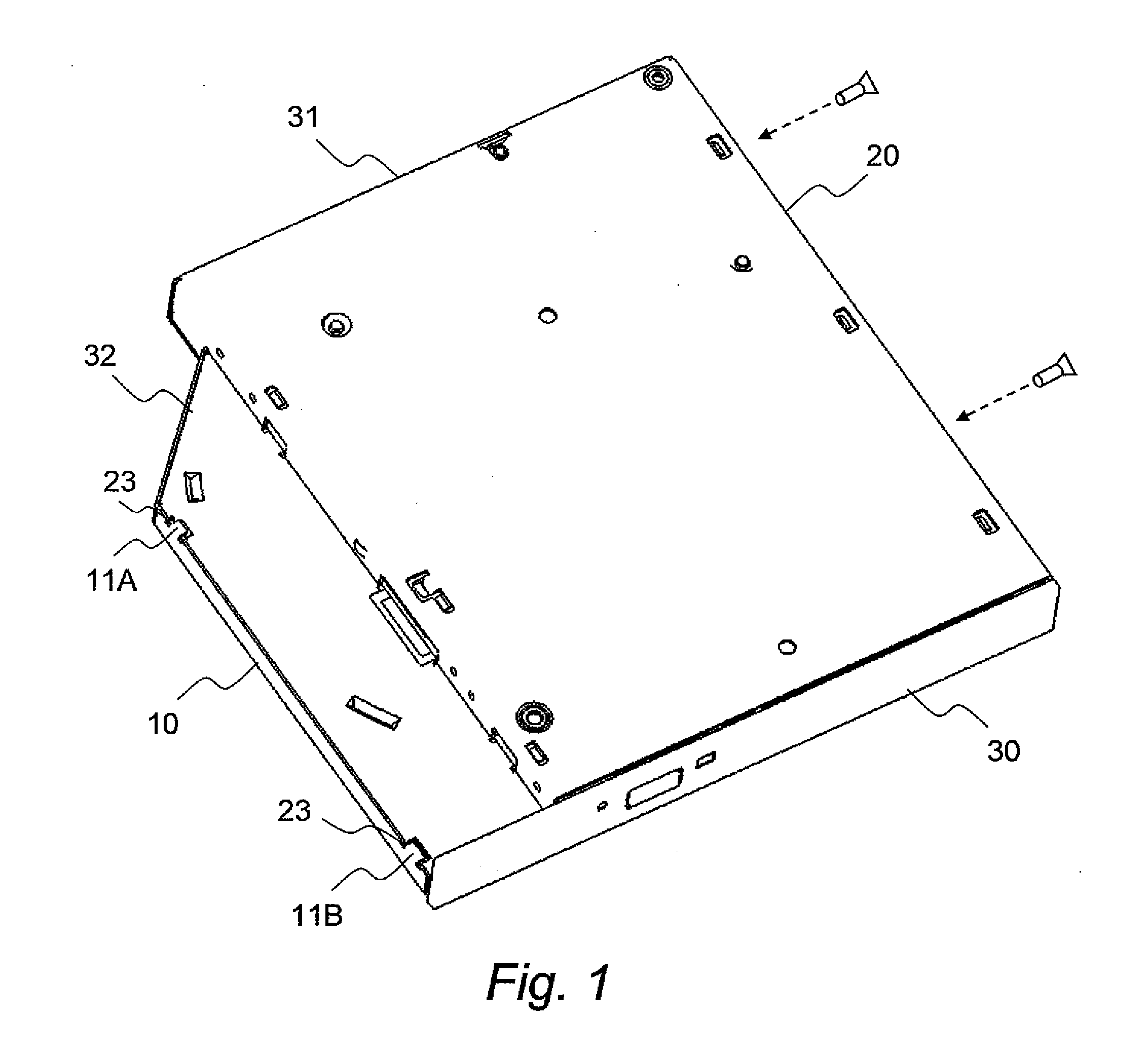
[0016]FIG. 1 is a perspective view illustrating an external appearance of an optical disk device according to an embodiment of this invention.

[0017]In an optical disk device according to this embodiment, a top case 10 and a bottom case 20 constitute a housing having a substantially box shape.

[0018]The housing illustrated in FIG. 1 is a so-called slim case which is separated into a body portion 31 having a large thickness and a wing portion 32 having a smaller thickness than that of the body portion. In addition, a front panel 30 is attached to a front surface side (front side) of the housing. The front panel 30 is attached to a tray on which a disk is loaded. The tray slides within the housing so as to eject or insert the disk which is loaded on the tray. In other words, when the tray is housed within the housing, the front panel 30 abuts the housing.

[0019]The top case 10 is provided with hooks 11A and 11B on a wing side (on a left side in FIG. 1). The hooks 11A and 11B engage with ...


PUM


Abstract

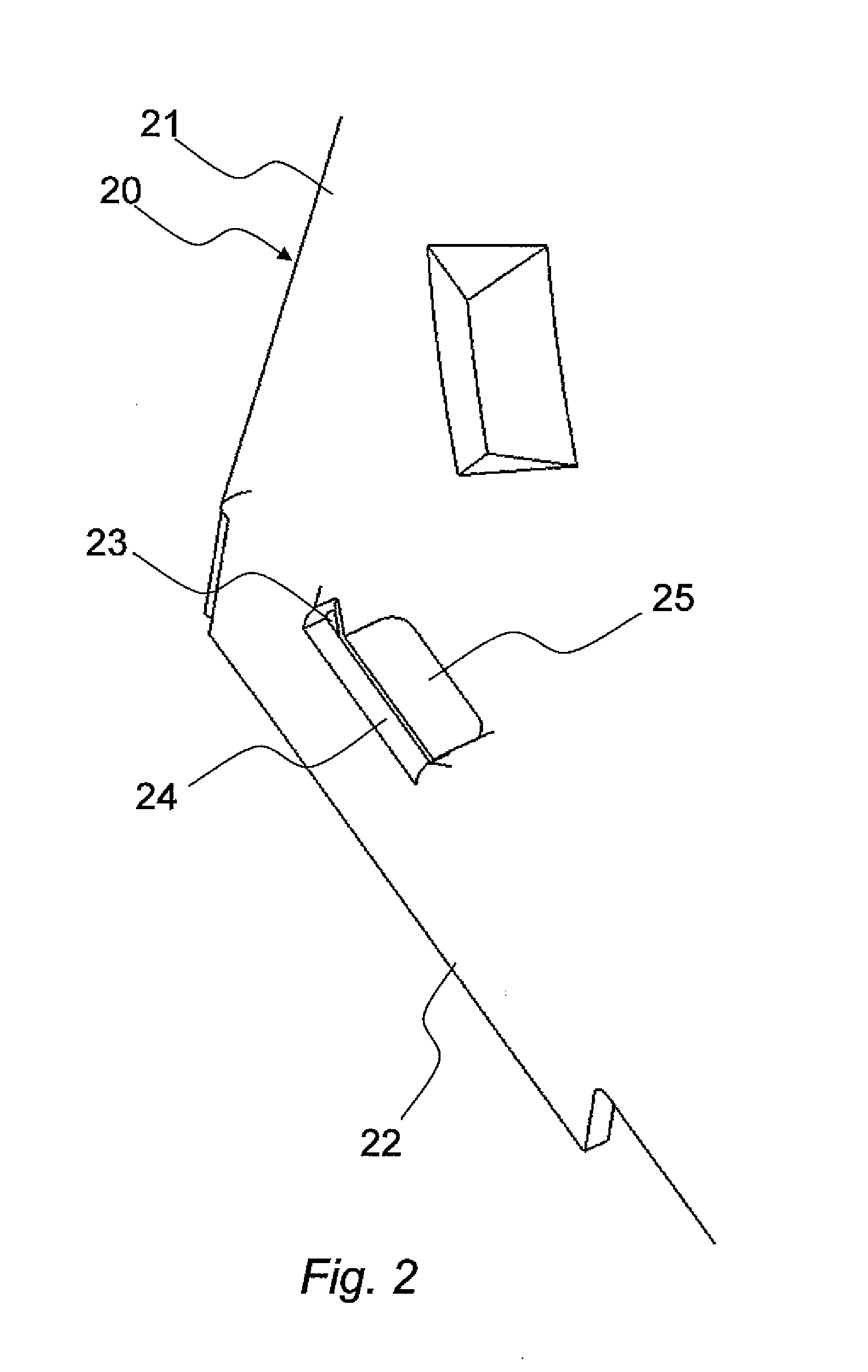
Provided is an optical disk device, including a top case and a bottom case which constitute a housing having a substantially box shape in which: the top case includes, on one side thereof, a hook which engages with the bottom case; the bottom case includes an engaging portion which is provided with a cutout which engages with the hook; and a shielding portion for preventing an air flow passing through the cutout is provided in an inside of the cutout.

Description

CLAIM OF PRIORITY[0001]The present application claims priority from Japanese patent application JP 2008-274110 filed on Oct. 24, 2008, the content of which is hereby incorporated by reference into this application.BACKGROUND OF THE INVENTION[0002]This invention relates to an optical disk device, and more particularly, to a structure of a housing with sound insulation properties being improved.[0003]An optical disk device, which reads and writes information on an optical disk such as a compact disk (CD), digital versatile disk (DVD), and Blu-ray disc (BD), has been thinner accordingly to miniaturization of a computer into which the optical disk device is installed. Therefore, there is a problem in which wind noise of the disk rotating within an inside of the optical disk device leaks easily to an outside of the optical disk device.[0004]In order to solve this problem, there has been proposed an optical disk device (for example, see JP2003-36664A). Specifically, in this optical disk d...

Claims


Application Information

Patent Timeline
IPC IPC(8): G11B33/02
CPCG11B33/022
Inventor MATSUMOTO, KOJIISHIZUKA, YOSUKE
Owner HITACHI-LG DATA STORAGE
Learn More