
Radio communication control device, radio communication system and radio communication terminal

a radio communication system and control device technology, applied in the field of radio communication control devices, radio communication systems and radio communication terminals, can solve the problems of limited network load reduction effect brought about by the system described in japanese laid-open patent publication no. 2000-174932, and achieve the effect of reducing the number, flexibly coping with arbitrary locations, and effectively utilizing limited radio resources

Inactive Publication Date: 2010-04-29
SONY CORP
View PDF13 Cites 17 Cited by
  • Summary
  • Abstract
  • Description
  • Claims
  • Application Information

AI Technical Summary

Benefits of technology

[0009]The present invention has been made in view of the circumstances as mentioned above. Therefore, it is desirable to dynamically and efficiently reduce the load on the radio communication network in accordance with a location and a time period.
[0012]According to an embodiment of the present invention, in the case that a call is made using a mobile phone terminal from within a jammed cell, a rule that an extra is added to the user's telephone call charge in accordance with a jammed state is first presented and then the intention of the user is confirmed so as to permit only the user whose intention has been confirmed to talk over the phone. That is, only a user who has admitted the addition of the extra to his telephone call charge is permitted to talk over the phone. As a result, it may be expected that the number of call-ups is reduced and the traffic jam is reduced.
[0017]According to an embodiment of the present invention, it may become possible to reduce the number of call transmitting and receiving operations, corresponding to an arbitrary time period for which a cell is jammed at an arbitrary location, for example, such as a shrine area in the New Year or a station and surrounding area in a rainy day. That is, it may become possible to effectively utilize a limited radio resource, flexibly coping with arbitrary location and time period.

Problems solved by technology

In the above mentioned case, voice calling may become difficult or may end in failure.
However, it may be difficult for the system to buy and sell the resource described in Japanese Laid-open Patent Publication No. 2002-217964 to cope with the fluctuation in traffic at a specific location and for a specific time period.
The network load reducing effect brought about by the system described in Japanese Laid-open Patent Publication No. 2000-174932 may be limited.
That is, the load on the network is merely reduced by the amount corresponding to the number of alternative wire networks and dynamic reduction of the load in a dealer's intended area may be difficult.

Method used


Image

  • Radio communication control device, radio communication system and radio communication terminal
  • Radio communication control device, radio communication system and radio communication terminal
  • Radio communication control device, radio communication system and radio communication terminal

Examples


Embodiment Construction

[0033]Next, preferred embodiments of the present invention will be described with reference to the accompanying drawings.

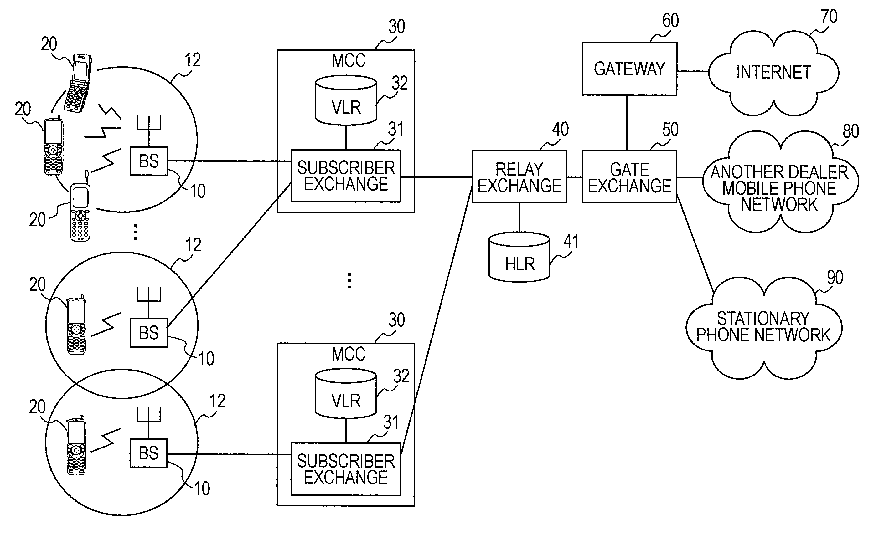
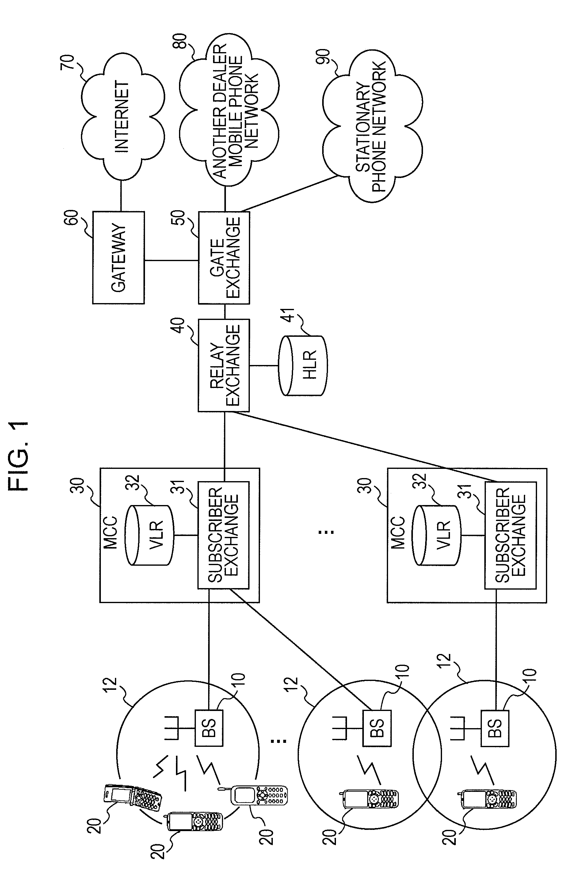
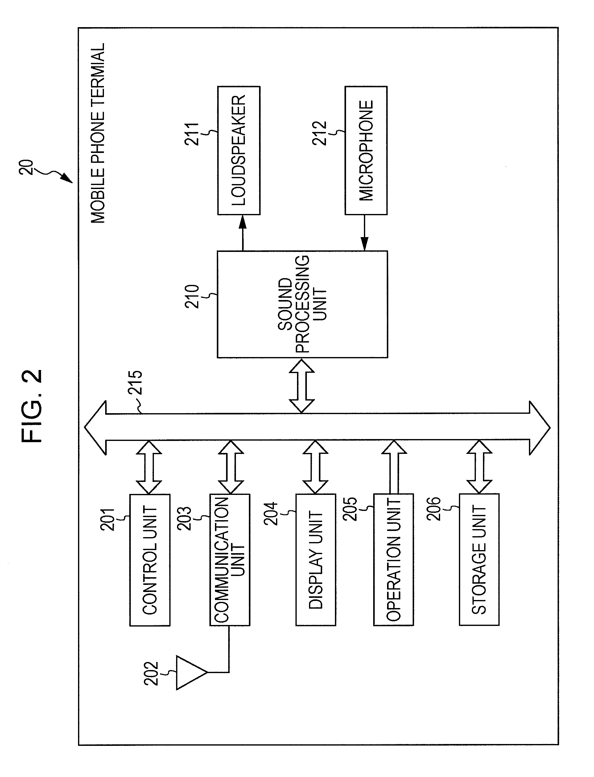
[0034]FIG. 1 illustrates a schematic configuration of a radio communication system according to an embodiment of the present invention. Although the entire configuration illustrated in FIG. 1 is referred to as a radio communication system in a broad sense, a single constitutional element illustrated in FIG. 1 or a combination of a plurality of constitutional elements illustrated in FIG. 1 may be referred to as a radio communication system defined in the appended patent claims. As a radio communication terminal according to an embodiment of the present invention, a mobile phone terminal having at least a talking-over-the-phone (hereinafter, referred to as talking) function will be described by way of example.

[0035]Each of a plurality of mobile phone terminals 20 performs radio communication, typically, with a neighboring base station (BS) 10. Each base station (BS)...


PUM


Abstract

A radio communication control device accepts a call-up from a radio communication terminal and includes a unit configured to detect the degree of jamming in a cell, a unit configured to confirm the intention of a user of a terminal concerned as to whether the call-up is continued regardless of addition of an extra to the user's telephone call charge when the call-up has been made from a radio communication terminal in the cell concerned in a specific jammed state, a unit configured to block the call-up concerned in accordance with the confirmed intention of the user of the terminal concerned and a unit configured to change charge setting so as to add an extra to the user's telephone call charge when the call-up has not been blocked in the specific jammed state.

Description

BACKGROUND OF THE INVENTION[0001]1. Field of the Invention[0002]The present invention relates to a radio communication system configured to realize talking over mobile phone terminals.[0003]2. Description of the Related Art[0004]In radio communication via mobile phones, although communication efficiency is increased with developing the communication technology, how a limited radio resource is efficiently utilized may still remain as a problem. As an example of an improving measure to eliminate this problem, there is proposed a system configured to buy and sell a resource in accordance with a fluctuation in traffic (see Japanese Laid-open Patent Publication No. 2002-217964).[0005]In addition, there is also proposed a mobile communication system configured such that the telephone call charge for intra-home-zone calls is made different from that for extra-home-zone calls in a radio communication network (see Japanese Laid-open Patent Publication No. 2000-174932). In this bulletin, ther...

Claims


Application Information

Patent Timeline
IPC IPC(8): H04W4/00H04W24/00H04W72/00H04W4/24
CPCH04L12/1421H04W28/0231H04M15/00H04M15/28H04M15/745H04M15/80H04M15/8022H04M15/8027H04M15/805H04M15/81H04M15/83H04M15/835H04M15/8351H04M15/85H04M15/851H04M15/858H04M15/88H04M15/883H04M2215/0108H04M2215/0112H04M2215/0116H04M2215/0128H04M2215/0168H04M2215/74H04M2215/7421H04M2215/7428H04M2215/7457H04M2215/81H04M2215/8104H04M2215/8108H04M2215/815H04M2215/8154H04M2215/8183H04M2215/82H04W4/24H04W4/26H04W28/12H04M15/58H04M15/66H04L12/1489H04W4/12H04K3/22H04K2203/16
Inventor NAKAI, TAKASHI
Owner SONY CORP
Learn More