Flexible clip applier

Active Publication Date: 2010-04-29
MICROLINE SURGICAL INC
View PDF30 Cites 18 Cited by
  • Summary
  • Abstract
  • Description
  • Claims
  • Application Information

AI Technical Summary

Benefits of technology

[0009]Accordingly, what is needed is a clip applier which can be used in a variety of endoscopic procedures including in an endoscope having a elongated channel that includes at least one curved port

Problems solved by technology

There are several disadvantages associated with conventional clip appliers as described and as currently used.
Therefore, these conventional clip appliers cannot extend through, e.g., an endoscope having an elongated channel that in

Method used


Image

  • Flexible clip applier
  • Flexible clip applier
  • Flexible clip applier

Examples


Example

[0037]The particulars shown herein are by way of example and for purposes of illustrative discussion of the embodiments of the present invention only and are presented in the cause of providing what is believed to be the most useful and readily understood description of the principles and conceptual aspects of the present invention. In this regard, no attempt is made to show structural details of the present invention in more detail than is necessary for the fundamental understanding of the present invention, the description taken with the drawings making apparent to those skilled in the art how the several forms of the present invention may be embodied in practice.

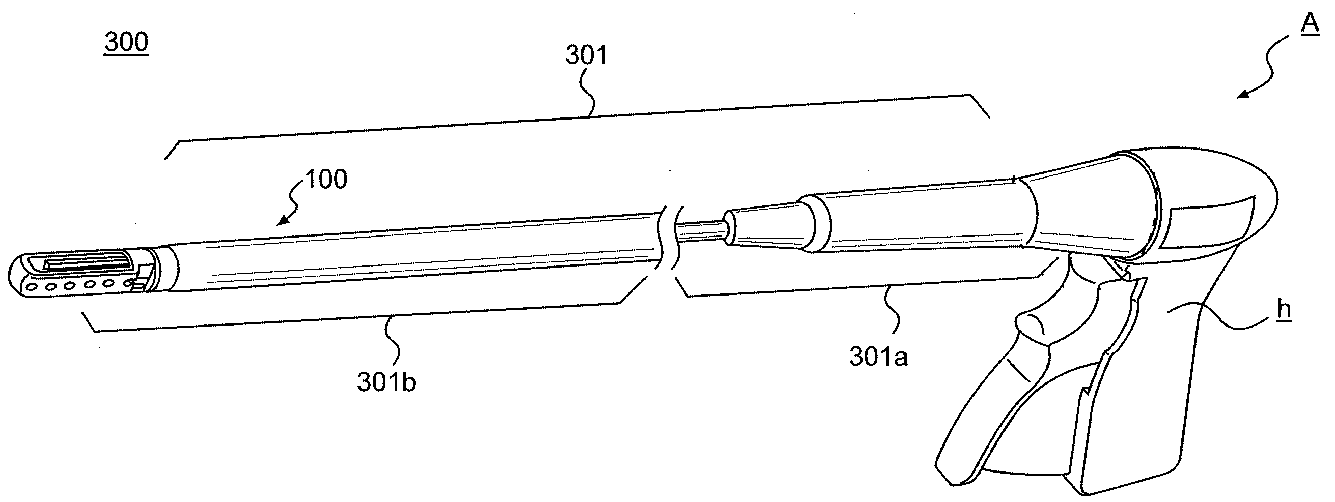
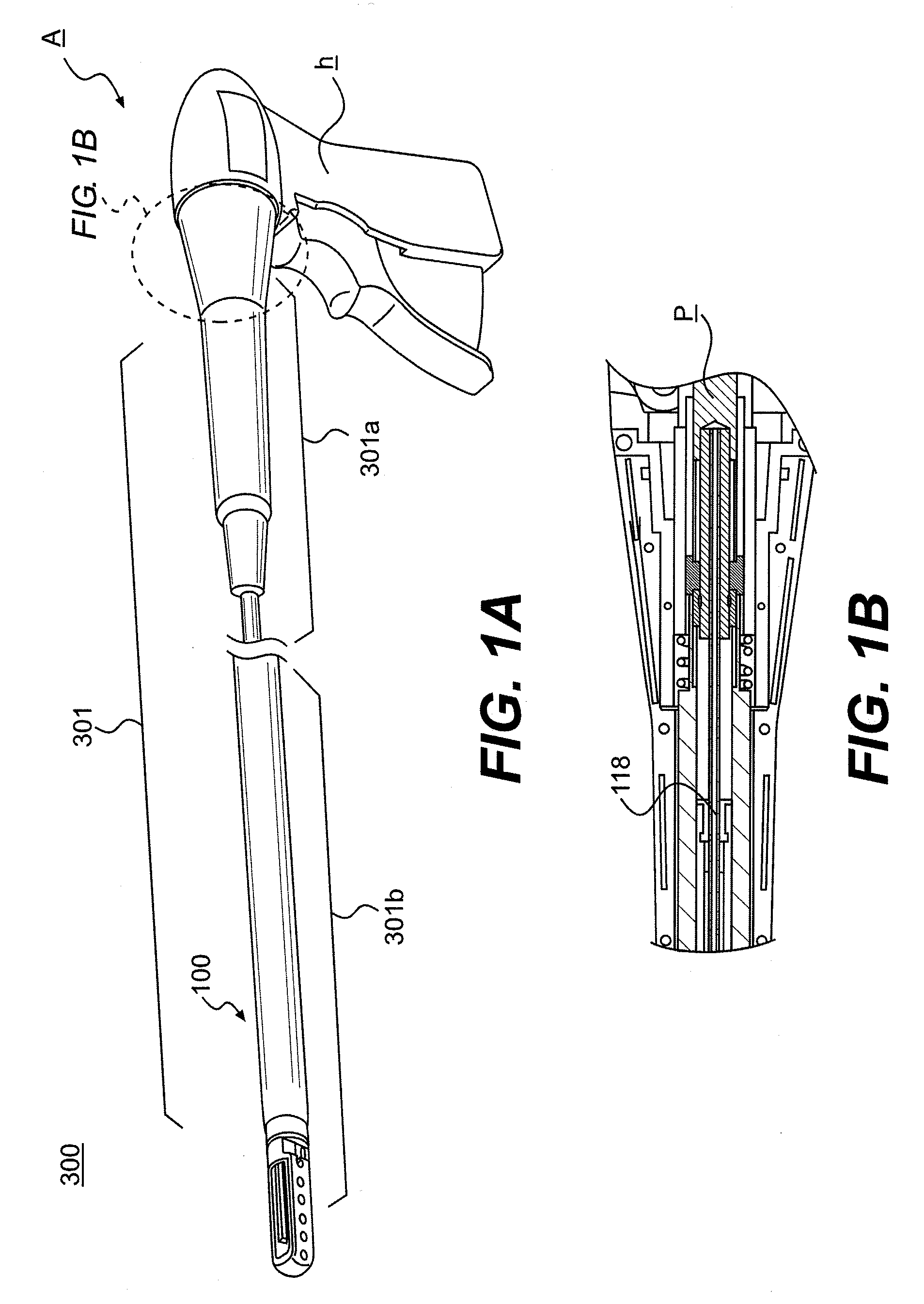
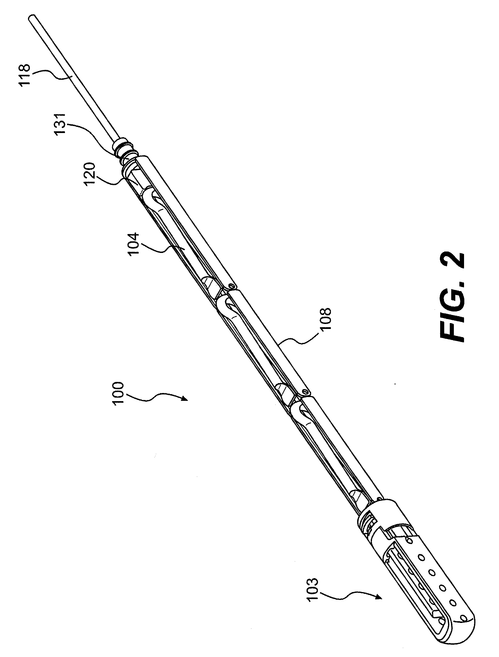
[0038]Referring to the drawings, FIG. 1 shows a flexible tool 100 of a clip applier 300 for applying a surgical clip (104, as shown in, e.g., FIG. 3) to a target area during a surgical procedure. In this regard, the clip applier 300 may include a shaft 301 having a proximal end 301a and a distal end 301b. Further, the dis...


PUM


Abstract

A clip applier includes a shaft having a proximal end and a distal end. Further, the distal end of the shaft includes a flexible tool having at least two rails connected to each other by at least one jointed connection, and the at least two rails configured to rotate about the jointed connection. Additionally, a pair of jaws may be provided at a distal end of the flexible tool. Further, an actuator may be provided at the proximal end of the shaft to advance the surgical clip within the flexible tool.

Description

BACKGROUND OF THE INVENTION[0001]I. Field of the Invention[0002]The present invention relates generally to a flexible clip applier for applying a surgical clip.[0003]II. Discussion of the Background Art[0004]Surgical instruments have been developed for use with a variety of endoscopic surgical techniques and procedures. In particular, in the conventional art, clip applier for occlusion and ligation of vessels are well known.[0005]Conventional clip appliers typically include an elongated body having a proximal end connected to an actuating mechanism, and a pair of jaws supported at the distal end.[0006]In one exemplary embodiment of a conventional art clip applier, the jaws include a pair of opposing jaw members which are movable with respect to each other. In this regard, the jaws may be configured to grasp a target area (e.g., a section of body tissue) therebetween. Thus, the jaws are moved relative to each other when an operator operates an actuating handle coupled to an actuating...

Claims


Application Information

Patent Timeline
IPC IPC(8): A61B17/10A61B19/00
CPCA61B17/00234A61B17/1227A61B2017/2905A61B2017/00292A61B17/1285
Inventor BOULNOIS, JEAN-LUCKAWANO, TOMOHIROSATO, MASAYASU
Owner MICROLINE SURGICAL INC
Why Eureka
Try Eureka