Optimized system voltage control method through coordinated control of reactive power source

a technology of reactive power source and integrated system, which is applied in the direction of electric variable regulation, process and machine control, instruments, etc., can solve the problems of large-scale power interruption, over-voltage and low voltage in the peripheral system, and unstable supply and demand of reactive power

Active Publication Date: 2010-04-29
KOREA ELECTRIC POWER CORP
View PDF12 Cites 35 Cited by
  • Summary
  • Abstract
  • Description
  • Claims
  • Application Information

AI Technical Summary

Benefits of technology

[0011]The present invention has been made in an effort to solve the above-described problems associated with the prior art, and an object of the present invention is to provide an optimized system voltage control method through coordinated control of reactive power source, which can solve the problem of an unstable reactive power supply, which is caused by an increase in power loss during long distance power transmission from a remote power source and a change in load characteristics of power consumers.

Problems solved by technology

Recently, the supply and demand of reactive power have become unstable due to an increase in power loss during long distance power transmission from a remote power source and a change in load characteristics of power consumers, which may cause a large-scale power interruption.
On the contrary, when an over-voltage occurs due to excessive reactive power in the power system, the capacitor for supplying the reactive power is interrupted, or the reactor for consuming the reactive power is used.
However, according to a conventional method for controlling the phase adjusting device, since the control operation is performed based on only the voltage of a bus(substation) in which the phase adjusting device is provided, there are possibilities that an over-voltage and a low voltage may occur in a peripheral system.
Moreover, an optimized control operation may not be performed due to the individual control and, since the control operation is performed for the purpose of simply maintaining the voltage, it causes an increase in the loss of the power system.

Method used


Image

  • Optimized system voltage control method through coordinated control of reactive power source
  • Optimized system voltage control method through coordinated control of reactive power source
  • Optimized system voltage control method through coordinated control of reactive power source

Examples


Embodiment Construction

[0032]Hereinafter, exemplary embodiments of the present invention will be described in detail below with reference to the accompanying drawings such that those skilled in the art to which the present invention pertains can easily practice the present invention.

[0033]Elements having similar structures and functions are designated by the same reference numerals refer to like elements having similar structures and functions throughout the specification.

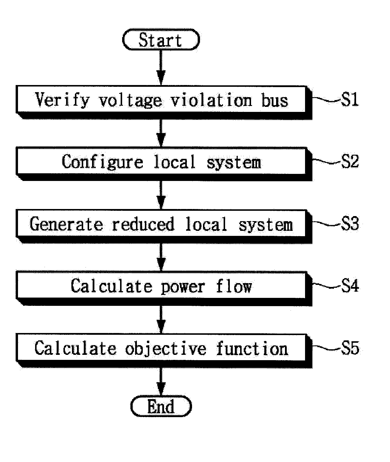
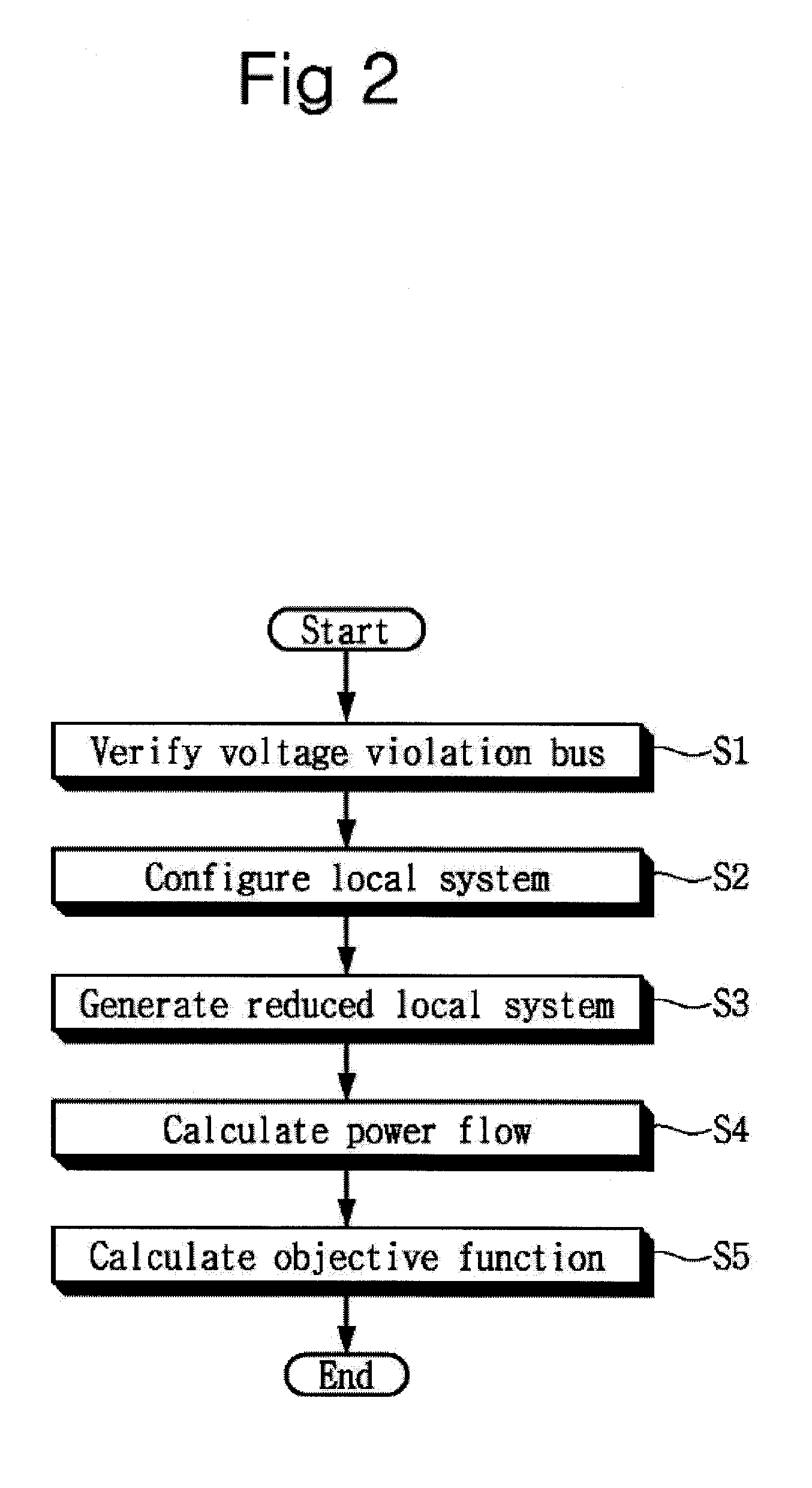
[0034]FIG. 2 is a flow chart illustrating an optimized system voltage control method through coordinated control of reactive power source in accordance with an embodiment of the present application

[0035]Referring to FIG. 2, the optimized system voltage control method through coordinated control of reactive power source includes a voltage violation bus verification step S1, a local system configuration step S2, a reduced local system generating step S3, a power flow calculation step S4 and an objective function calculation step S5.

[0036]T...


PUM


Abstract

Provided is an optimized system voltage control method through coordinated control of reactive power source, which analyzes the location for reactive power compensation and the effect of applying compensation equipment by calculating the reactive power and voltage sensitivity of a power system, thus improving the voltage quality of the power system.The optimized system voltage control method includes verifying a voltage violation substation having a voltage exceeding a predetermined voltage reference value among buses of a test system on a computer program, configuring a local system with eight to ten substations with respect to the verified voltage violation substation, generating a reduced local system using a reduced local algorithm with respect to the buses within the configured local system, calculating a power flow by determining a voltage control amount for restoring the voltage of the voltage violation substation to a normal value with respect to the reduced local system, and calculating an optimization objective function value based on the voltage control amount and control operation.

Description

CROSS-REFERENCE TO RELATED APPLICATION[0001]This application claims priority to and the benefit of Korean Patent Application No. 2008-0106744, filed on Oct. 29, 2008, the disclosure of which is incorporated herein by reference in its entirety.BACKGROUND[0002]1. Field of the Invention[0003]The present application relates to an optimized system voltage control method through coordinated control of reactive power source, and more particularly, to an optimized system voltage control method through coordinated control of reactive power source, which analyzes the location for reactive power compensation and the effect of applying compensation equipment by calculating the reactive power and voltage sensitivity of a power system, thus improving the voltage quality of the power system.[0004]2. Discussion of Related Art[0005]Recently, the supply and demand of reactive power have become unstable due to an increase in power loss during long distance power transmission from a remote power source...

Claims


Application Information

Patent Timeline
Patent Type & Authority Applications(United States)
IPC IPC(8): G06F1/28G06F17/10G06G7/63
CPCG06F1/305H02J3/00H02J3/06
Inventor NAM, SU-CHULSHIN, JEONG-HOONCHA, SEUNG-TAELEE, JAE-GULKIM, TAE-KYUN
Owner KOREA ELECTRIC POWER CORP
Why Eureka
Try Eureka