Soleplate for an iron

a soleplate and iron technology, applied in the field of soleplates for irons, can solve the problems of water spillage risk and/or antibacterial components, and achieve the effect of facilitating the transfer of metal ions

Inactive Publication Date: 2010-05-06
KONINKLIJKE PHILIPS ELECTRONICS NV
View PDF7 Cites 3 Cited by
  • Summary
  • Abstract
  • Description
  • Claims
  • Application Information

AI Technical Summary

Benefits of technology

[0057]Steam may for example be provided to the garment surface by a steam ironing device or a steamer during use or by hanging the garment in a damp room, such as the bathroom after somebody has taken a shower. Using the steam ironing device is an easy way to further facilitate the transfer of metal ions from the garment-contact surface of the soleplate of the iron to the garment surface. While being ironed using the steam function on the iron, the garment surface is moistened by the steam and contacted by the garment-contact surface comprising the antimicrobial agent of the iron at the same time.
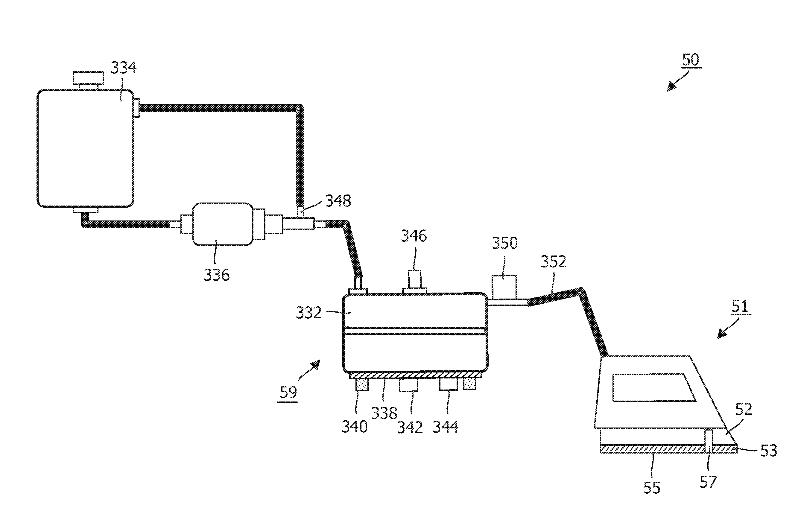
[0058]The steam ironing device as such is well-known in practice. The steam ironing device may be a steam iron or a so-called boiler ironing system. The boiler ironing system comprises a steam iron having a soleplate with a soleplate surface and a boiler for heating water which is arranged separately from the steam iron, wherein the water tank is attached to a stand comprising the boiler. In many cases, the water tank is removably arranged, so that a user of the device comprising the water tank is capable of taking the water tank to a tap or the like in order to fill the water tank, without having to move the entire device.

Problems solved by technology

This may be cumbersome and there is a risk of spilling water and / or the antibacterial member.

Method used


Image

  • Soleplate for an iron
  • Soleplate for an iron
  • Soleplate for an iron

Examples


example 2

[0104]The steps for the manufacturing of the reference soleplate were followed, according to which the mixture of the sol-gel top coating is admixed with an AgION® ethanol solution (ratio of 30:70% by weight). In this way an antibacterial sol-gel mixture is obtained comprising approximately 8% AgION®.

[0105]Because the sol-gel mixture is alcohol-based, an alcohol-compatible AgION® powder was used.

[0106]A skilled person may select a different weight ratio, if preferred.

[0107]Subsequently the plate was dried and cured. This way soleplate S3 was obtained, this soleplate had an antimicrobial topcoat layer of about 10 micron in thickness.

example 3

[0108]A water-based AgION® slurry is mixed with a Teflon™ (by Du Pont)-based Ceralon (by Whitford) coating.

[0109]This 2.5% by weight solid AgION® mixture is applied on top of the aluminum soleplate by spraying. The Ceralon coating is a water-based coating; in order to obtain a mixture, water-based AgION® (slurry) was used. The layer thus obtained was dried and cured. In this way soleplate S4 was obtained.

Ironing Tests

[0110]Sole plates S1-S3 were used on Azur irons from Philips.

[0111]Sole plate S4 was used on a Mistral iron from Philips.

[0112]All irons used are steam irons, the steaming function was however turned off in some experiments.

[0113]All samples described were tested in one run.

[0114]Pieces of standard cloth (each cut from the same moiré fabric of 0.4 g / m) were cut, (approximately 13.5×approximately 66.5 cm) and were subjected to the following treatments:[0115]1) Washing;[0116]2) Ironing using one of the soleplates 1-4 prepared as described above;[0117]3) After 3 days the p...


PUM

PropertyMeasurementUnit
temperatureaaaaaaaaaa
temperaturesaaaaaaaaaa
temperatureaaaaaaaaaa

Abstract

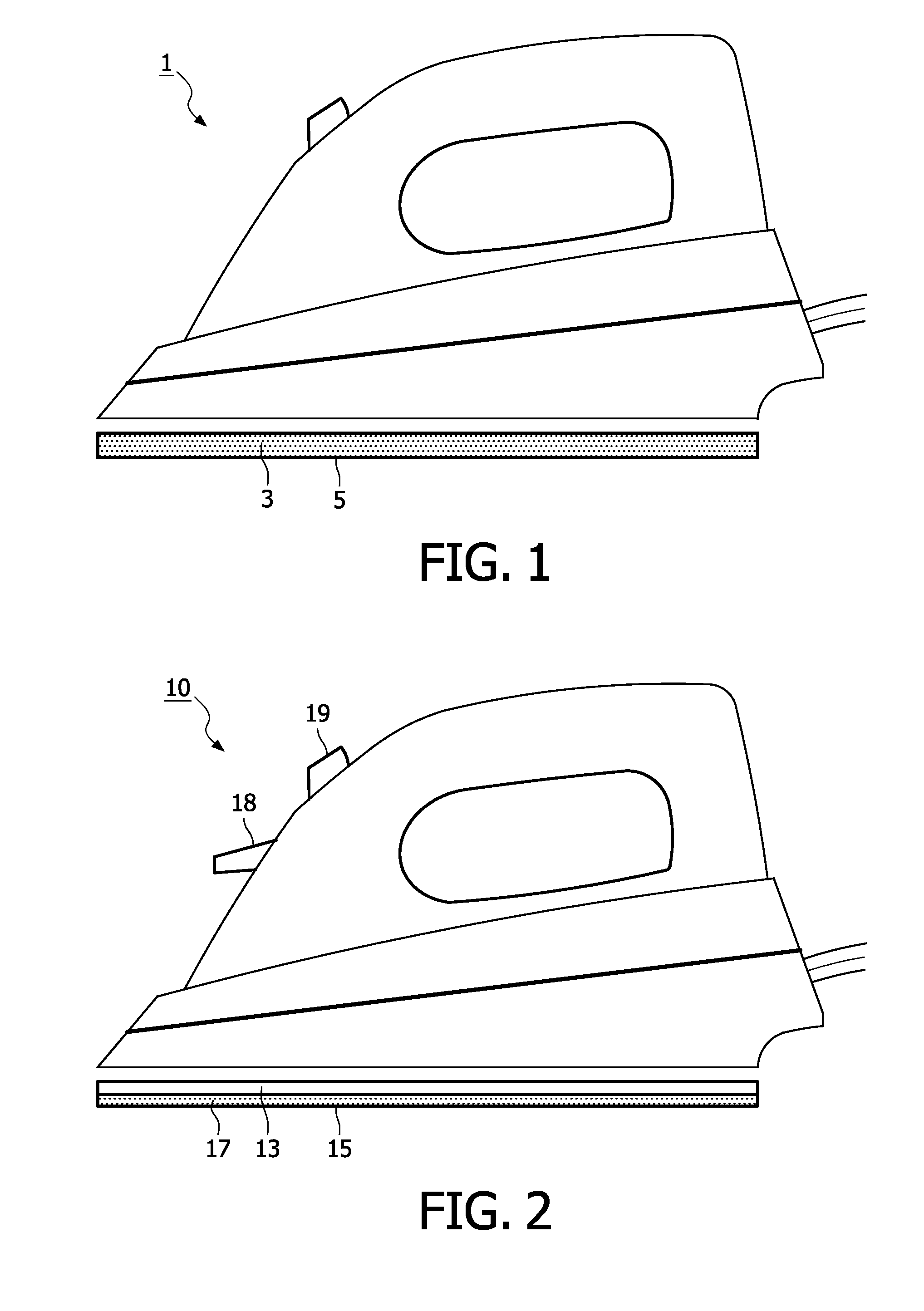
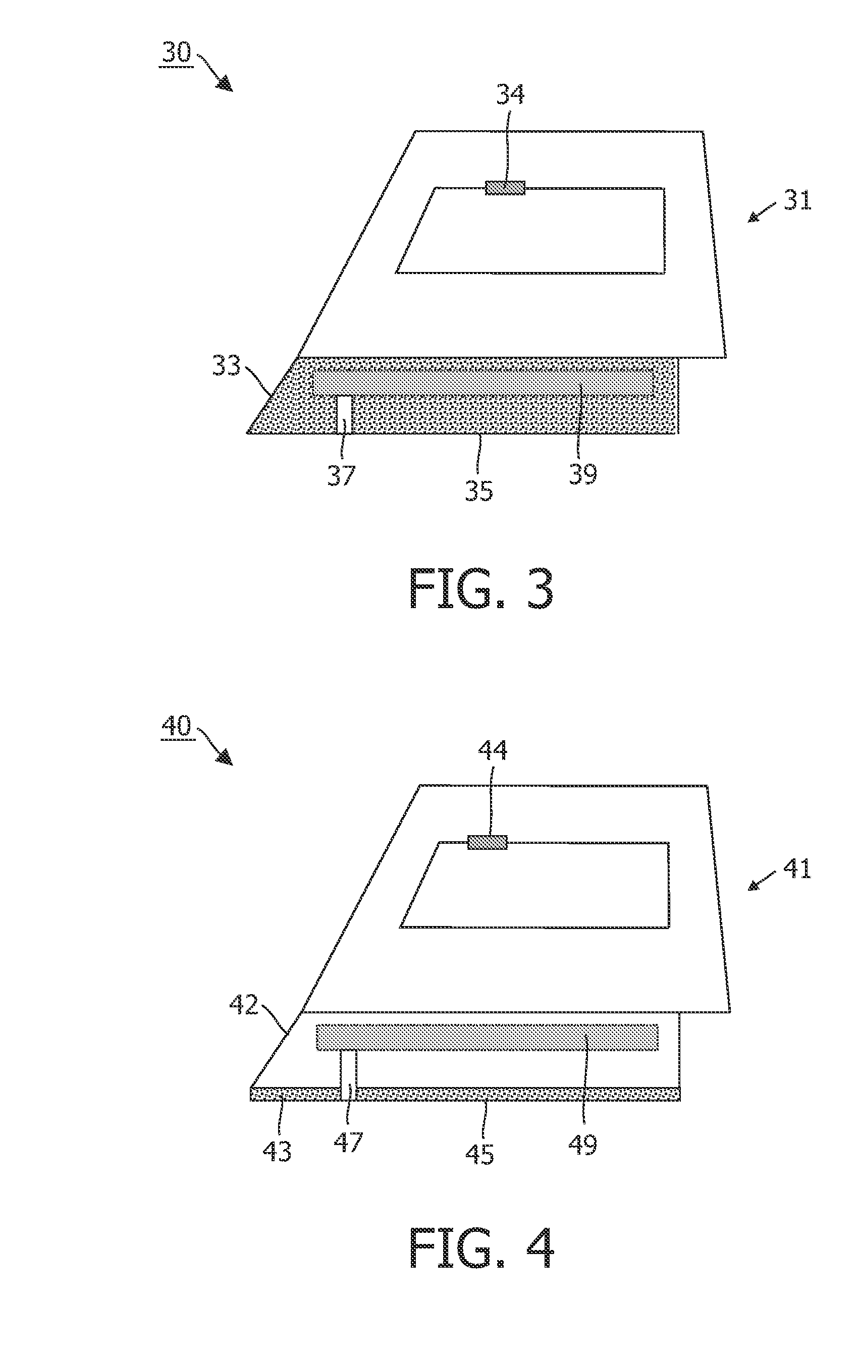
The invention relates to an iron (1) comprising a soleplate (3) having a garment-contact surface (5) and having a means for accommodating an antimicrobial agent. By contacting the garment-contact surface with the piece of garment, as is being done during ironing, the antibacterial agent is transferred to the garment. The antimicrobial agent is disposed on the garment by simply placing the iron on the garment and moving it over the garment surface. The garment stays fresher for a longer period of time. The invention further relates to a soleplate, a steam ironing device and methods of manufacturing an iron and a soleplate, respectively.

Description

FIELD OF THE INVENTION[0001]The invention relates to an iron comprising a soleplate having a garment-contact surface and having a means for accommodating an antimicrobial agent. The invention further relates to a soleplate, a steam ironing device, and a method of manufacturing an iron and a method of manufacturing a soleplate.DESCRIPTION OF THE PRIOR ART[0002]An embodiment of the above-described iron is known from JP-09056997.[0003]JP-09056997 discloses a steam iron comprising a main body and a base equipped with a heater and a steam-jetting hole and a predetermined amount of water and an antibacterial member provided in a water feed tank. By jetting steam containing the antibacterial member from the lower surface of the iron base the antibacterial member is applied to clothing.[0004]The user has to fill and refill the water feed tank of such an iron with water and the antimicrobial agent to ensure the availability of the antimicrobial agent. This may be cumbersome and there is a ri...

Claims


Application Information

Patent Timeline
Patent Type & Authority Applications(United States)
IPC IPC(8): D06F75/20D06F75/38B23P19/04
CPCY10T29/53D06F75/38
Inventor NATHAMUNI BALAJI, VIGNESHJIANG, YONGWERKMAN, PIETER JOHANNESVAN DEN BOOGAARD, MAARTEN
Owner KONINKLIJKE PHILIPS ELECTRONICS NV
Why Eureka
Try Eureka